Eureka AIR delivers breakthrough ideas for toughest innovation challenges, trusted by R&D personnel around the world.

A dust removal device and dust removal method for dusty oil and gas

A dust removal device, oil and gas technology, applied in separation methods, combined devices, chemical instruments and methods, etc., can solve the problems of low dust collection efficiency, increased pressure drop inside and outside the membrane tube, and cyclone dust collector pressure drop, etc. Achieve the effect of reducing oil and gas dust content and tar yield

Active Publication Date: 2020-04-28
XI AN JIAOTONG UNIV
View PDF10 Cites 0 Cited by
  • Summary
  • Abstract
  • Description
  • Claims
  • Application Information

AI Technical Summary

Problems solved by technology

At present, multi-stage wet combined separation and cyclone separation technologies are generally used in actual projects in my country, which have problems such as large pollution, high energy consumption, and cumbersome follow-up treatment, and the pressure drop of cyclone dust collectors is generally high. The collection efficiency is low, so the general cyclone dust collector can only be used as a pre-dust removal equipment
Filtration and dust removal technology has become a research hotspot in the field of high temperature dust removal due to its low heat loss and high efficiency. However, the existence of a large amount of fine coke powder in actual operation causes high load operation of the filter material, so the load intensity of the filter material is reduced and the filter material is extended. Filtration stability is a key issue to be solved in the field of coal chemical industry
In addition, during the process of coal pyrolysis, the pyrolysis oil and gas contain a large amount of macromolecular volatiles. These macromolecular volatiles are easy to condense or form soot at higher temperatures, and adhere to the surface of the filter material or deposit on the aggregate of the filter material. In the channel, the pressure drop between the inner and outer layers of the membrane tube increases

Method used


Image

  • A dust removal device and dust removal method for dusty oil and gas
  • A dust removal device and dust removal method for dusty oil and gas
  • A dust removal device and dust removal method for dusty oil and gas

Examples


Embodiment

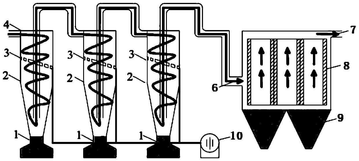
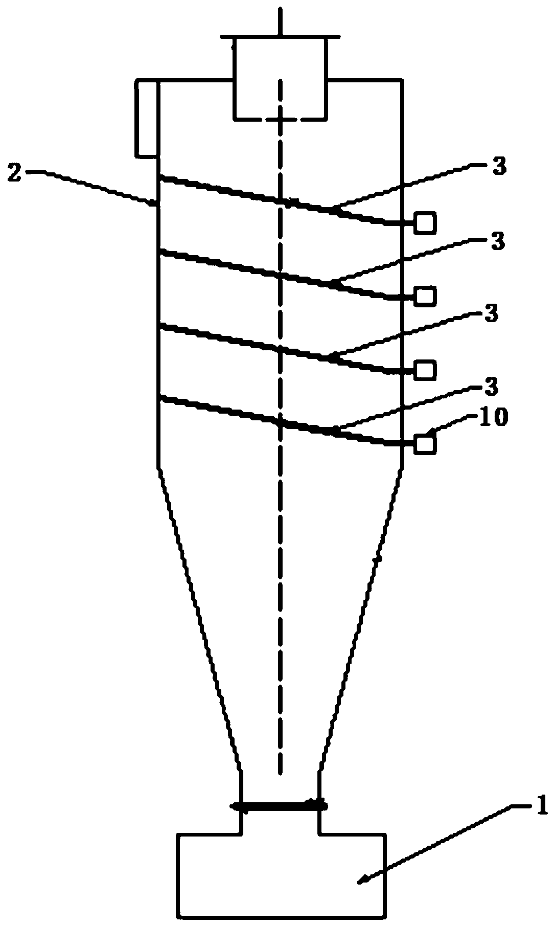
[0052] see figure 1 and figure 2 In the following, the technical scheme of the present invention will be further described in detail by taking the medium-low temperature pyrolysis of low-rank coal as an example. A kind of dedusting method of dusty oil gas of the present invention specifically comprises the following steps:

[0053] (1) Low-rank coal is pyrolyzed through the pyrolysis furnace at medium and low temperature to produce pyrolysis oil and gas with high temperature and high dust content at 500-800°C, which enters the third-stage catalytic sieve cyclone separation through the air inlet of the first-stage catalytic sieve cyclone separator The device is used for large particle filtration and preliminary catalysis stage to capture fly ash and dust particles above 5 μm, and at the same time, the macromolecular gas products are converted to small molecular gas products under catalytic conditions, reducing the tar yield and increasing the synthesis gas yield, and obtainin...


PUM


Abstract

The invention discloses a dust removal device and method for oil and gas containing dust. The dust removal device comprises a multi-stage cyclone separation system and a filter type catalytic separation system. An air inlet of the multi-stage cyclone separation system is used for introducing the oil and gas containing the dust, and an air outlet of the multi-stage cyclone separation system is in communication with an air inlet of the filter type catalytic separation system. An air outlet of the filter type catalytic separation system is used for outputting clean oil and gas after dust removal.A filter material of the filter type catalytic separation system is an inorganic membrane filtration material. The multi-stage cyclone separation system comprises a plurality of cyclone separators which communicate in sequence. One or more stages of catalytic sieve plates is or are arranged in a cylinder body of each of the cyclone separators in the tangential direction of cyclone flow. The catalytic sieve plates are of porous plate structures, and the surfaces of the catalytic sieve plates are loaded with catalysts. The dust removal device and method can realize the fractional separation coupling synchronous catalysis of high-temperature and high-dust oil and gas, and can realize the conversion of oil and gas macromolecular volatiles to small molecules while removing particulate dust.

Description

technical field [0001] The invention belongs to the technical field of resource recovery of fine particle organic matter and gas-solid separation, and in particular relates to a dust removal device and a dust removal method for dusty oil and gas. Background technique [0002] The pyrolysis technology of organic matter (such as coal and biomass) is one of the important ways for efficient and clean resource utilization. Taking coal as an example, coal pyrolysis technology is the core technology for clean and efficient conversion of coal, but the coke powder and ash particles contained in oil and gas during the coal pyrolysis process are one of the main factors restricting the clean pyrolysis utilization of coal. In the pyrolysis of pulverized coal, the content of particulate matter is large, and the composition of coal pyrolysis oil is complex, of which more than 80% are aromatic compounds. These macromolecular hydrocarbons are very easy to condense, and the pyrolysis oil is e...

Claims


Application Information

Patent Timeline
Patent Type & Authority Patents(China)
IPC IPC(8): B01D50/00B01D46/00B01D45/16B01D53/75B01D53/86
Inventor 高宁博李宗阳全翠
Owner XI AN JIAOTONG UNIV
Why Eureka
Eureka Blog
Learn More