


Quick Research
Generate reliable direction feasibility study reports for your R&D in just a few steps.

Technical Q&A
Discover and master advanced knowledge NOW. Basics, ideas, possibilities, all at once.

Find Solutions
As an expert in R&D theories, this can generate solutions to your technical problems instantly.

Evaluate Feasibility
Analyze your overall solution with one click, know your potential R&D risks in advance.

Monitor Landscape
Get weekly tech updates, stay abreast of the latest tech innovations and key insights.
Duplexer
A duplexer and resonator technology, which is applied in the field of semiconductors and micro-electromechanical systems, can solve the problems that the performance of resonators is difficult to guarantee, difficult to adjust, and limit the overall performance of filters, etc., and achieve the effect of wide adjustment range
- Summary
- Abstract
- Description
- Claims
- Application Information
AI Technical Summary
Problems solved by technology
Method used
Image

Examples
Embodiment 1
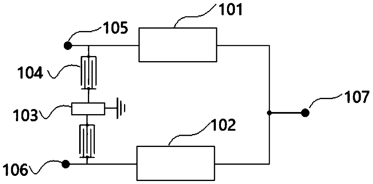
[0057] figure 1 A block diagram of the duplexer of the first embodiment of the present application is shown. like figure 1 As shown, a duplexer includes:
[0058] a transmit filter 101 connected between the transmit end 105 and the antenna end 107 and comprising series resonators and parallel resonators connected in a ladder form; and
[0059] A receiving filter 102, the receiving filter 102 is connected between the receiving end 106 and the antenna end 107,
[0060] Wherein, the transmitting end 105 and the receiving end 106 respectively lead out a branch to the grounding end, and the LWR resonator 104 and the passive device 103 are connected in series in the branch.
[0061] Wherein, each passive device 103 may be a capacitor, an inductor or a resonator. The structure of the passive device 103 can be T-type, pi-type and L-type structures.
[0062] The above-mentioned duplexer adds an LWR resonator channel between the transmitting end 105 and the receiving end 106, where...
Embodiment 2
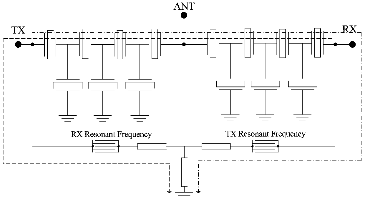
[0091] Figure 7 A block diagram of the duplexer of the second embodiment of the present application is shown. like Figure 7 As shown, a duplexer includes:
[0092] a transmit filter 101 connected between the transmit end 105 and the antenna end 107 and comprising series resonators and parallel resonators connected in a ladder form; and
[0093] A receiving filter 102, the receiving filter 102 is connected between the receiving end 106 and the antenna end 107,
[0094] Wherein, the transmitting terminal 105 leads out a branch to the ground terminal, and the LWR resonator 104 and the passive device 103 are connected in series in the branch.
[0095] Wherein, each passive device 103 may be a capacitor, an inductor or a resonator. The structure of the passive device 103 can be T-type, pi-type and L-type structures.
[0096] Figure 8 A circuit structure diagram of the duplexer according to the second embodiment of the present application is shown. like Figure 8 As shown...
Embodiment 3
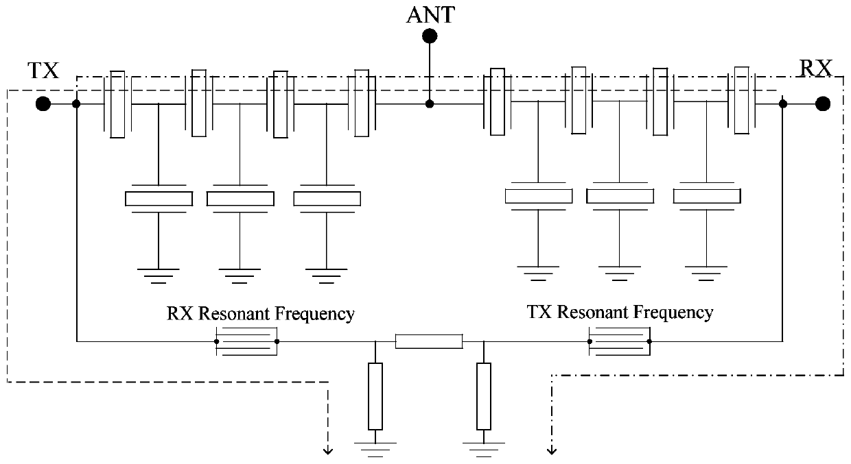
[0105] Figure 11 A block diagram of the duplexer of the third embodiment of the present application is shown. like Figure 11 As shown, a duplexer includes:
[0106] a transmit filter 101 connected between the transmit end 105 and the antenna end 107 and comprising series resonators and parallel resonators connected in a ladder form; and
[0107] A receiving filter 102, the receiving filter 102 is connected between the receiving end 106 and the antenna end 107,
[0108] The receiving end 106 leads out a branch to the ground end, and the LWR resonator 104 and the passive device 103 are connected in series in the branch.
[0109] Wherein, each passive device 103 may be a capacitor, an inductor or a resonator. The structure of the passive device 103 can be T-type, pi-type and L-type structures.
[0110] Figure 12 A circuit structure diagram of a duplexer according to the third embodiment of the present application is shown. like Figure 12 As shown, a duplexer includes:...
PUM
 Abstract
Description
Claims
Application Information
 - R&D Engineer
- R&D Manager
- IP Professional
- Industry Leading Data Capabilities
- Powerful AI technology
- Patent DNA Extraction
Browse by: Latest US Patents, China's latest patents, Technical Efficacy Thesaurus, Application Domain, Technology Topic, Popular Technical Reports.
© 2024 PatSnap. All rights reserved.Legal|Privacy policy|Modern Slavery Act Transparency Statement|Sitemap|About US| Contact US: help@patsnap.com