High-extension cold-rolled ribbed steel bar workpiece manufacturing device
A cold-rolled ribbed steel bar and manufacturing device technology, which is applied in the field of steel bar manufacturing machinery, can solve the problems of irregular overall shape and structure of steel bar workpieces, difficult forming of steel bar workpieces, and large force effects, etc., to achieve regular shape and structure. Uniform force structure and good mechanical properties
- Summary
- Abstract
- Description
- Claims
- Application Information
AI Technical Summary
Problems solved by technology
Method used
Image
Examples
Embodiment 1
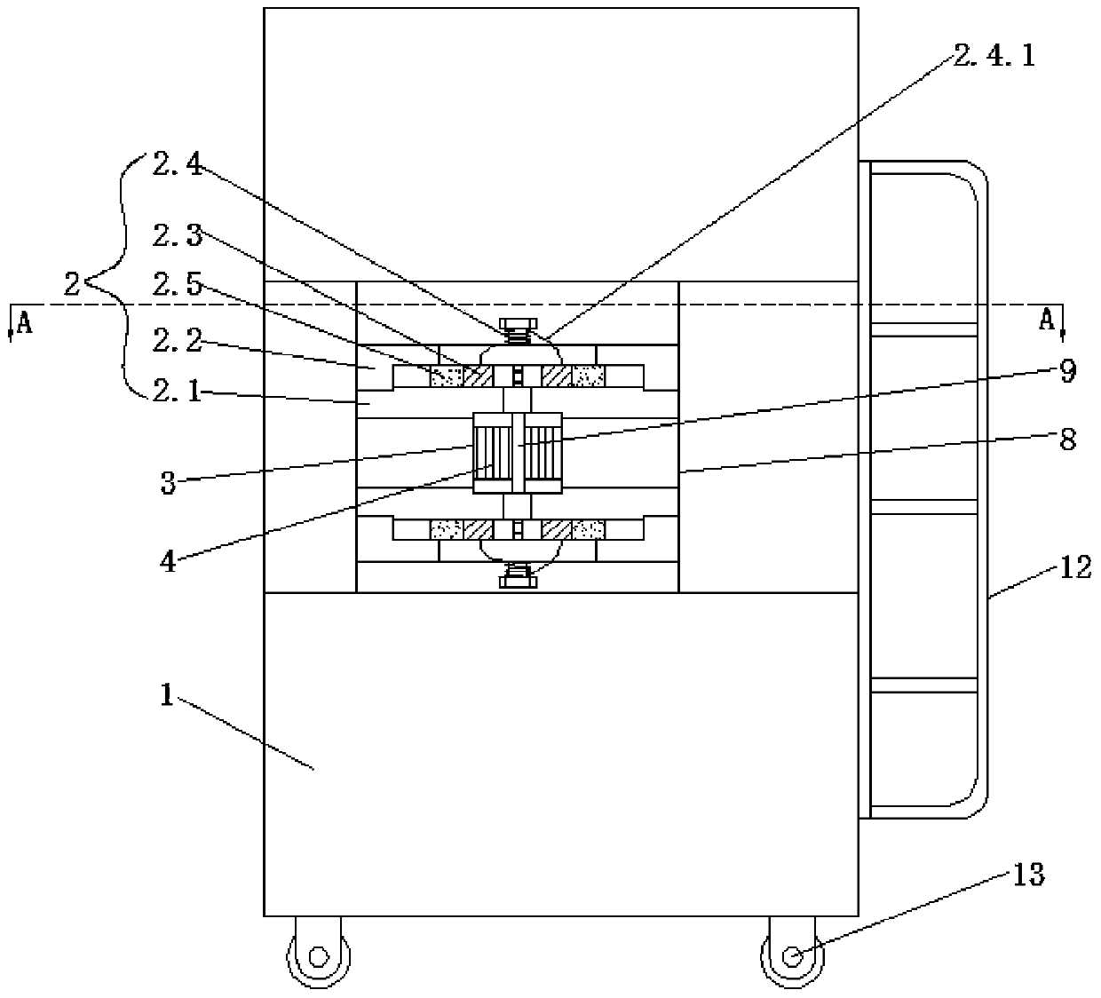
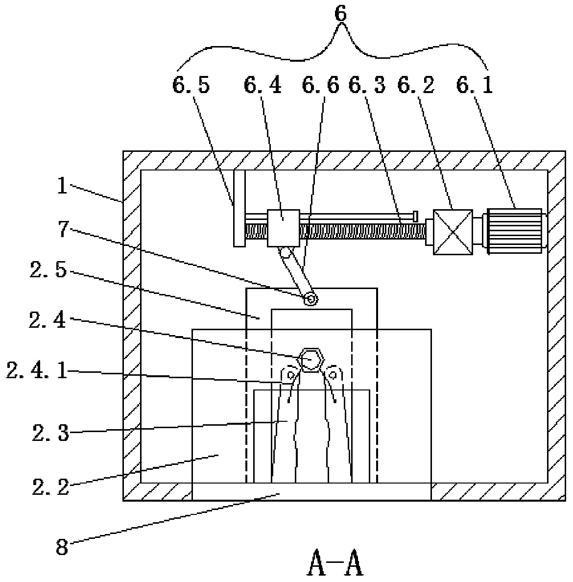
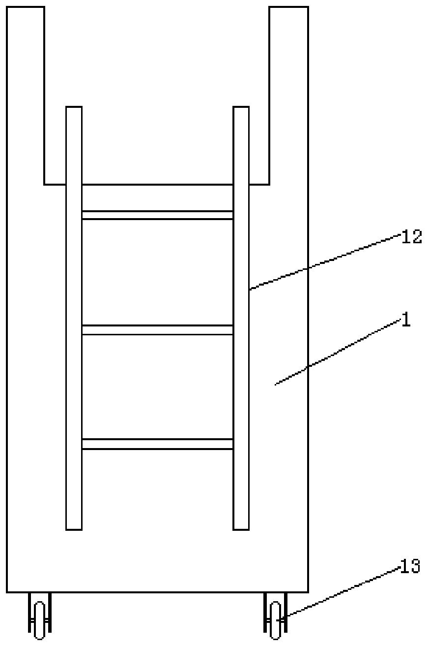
[0032] Such as Figures 1 to 6As shown, the present embodiment provides a high-elongation cold-rolled ribbed steel bar workpiece manufacturing device, including a casing 1, which is provided with an upper clamping mechanism 2 and a lower clamping mechanism for fixing steel bars, the upper clamping The mechanism 2 and the lower clamping mechanism are symmetrically arranged up and down. A twisting sleeve 3 is arranged between the upper clamping mechanism 2 and the lower clamping mechanism. Inside the twisting sleeve 3, there is a clamping hole 3.1 that allows steel bars to pass through. The twisting sleeve 3. A number of driven teeth 4 are evenly distributed on the outer wall in the circumferential direction, and the torsion sleeve 3 is engaged with the driving gear 5.
[0033] In this embodiment, when making steel bars, first select two suitable steel bars to pass through the upper clamping mechanism, the twisting sleeve and the lower clamping mechanism in turn, and the two ste...
Embodiment 2
[0035] Such as Figures 1 to 5 As shown, this embodiment is further optimized on the basis of embodiment 1. Specifically, the upper clamping mechanism 2 includes a seat plate 2.1 fixed in the casing 1, and the bottom of the seat plate 2.1 is provided with a matching torsion sleeve 3 A rotating circular groove, a cover plate 2.2 is arranged above the seat plate 2.1, two left and right symmetrical clamping pieces 2.3 are hinged between the cover plate 2.2 and the seat plate 2.1, a torsion spring 2.4 is arranged on the top of the cover plate 2.2, and the torsion spring 2.4 Two spring wires 2.4.1 extend out and are respectively connected to the top of the corresponding clamping part 2.3. The two clamping parts 2.3 have a tendency to rotate in the opposite direction under the action of the corresponding spring wire 2.4.1, and the seat plate 2.1 has limited settings. The position U-shaped plate 2.5, the two clamping parts 2.3 are located in the U-shaped groove of the limit U-shaped ...
Embodiment 3
[0038] Such as Figures 1 to 5 As shown, this embodiment is further optimized on the basis of embodiment 2. Specifically, the side wall of the casing 1 is provided with an observation port 8 facing the upper clamping mechanism 2, the lower clamping mechanism and the torsion sleeve 3. , the torsion sleeve 3 is provided with a vertical positioning slot 9, the driving gear 5 is connected with the second reducer 10 through the transmission shaft, the second reducer 10 is connected with the second motor 11, the driving gear 5, the second Both the reducer 10 and the second motor 11 are inside the casing 1 .
[0039] In this embodiment, the driving gear can drive the torsion sleeve to rotate by starting the second motor. The observation port provided on the side wall of the casing is to facilitate the observation of the fixing of the internal steel bars. There is a vertical arrangement on the torsion sleeve. Positioning through slot, every time the positioning through slot passes th...
PUM
 Abstract
Description
Claims
Application Information
 - R&D
- Intellectual Property
- Life Sciences
- Materials
- Tech Scout
- Unparalleled Data Quality
- Higher Quality Content
- 60% Fewer Hallucinations
Browse by: Latest US Patents, China's latest patents, Technical Efficacy Thesaurus, Application Domain, Technology Topic, Popular Technical Reports.
© 2025 PatSnap. All rights reserved.Legal|Privacy policy|Modern Slavery Act Transparency Statement|Sitemap|About US| Contact US: help@patsnap.com


