


Quick Research
Generate reliable direction feasibility study reports for your R&D in just a few steps.

Technical Q&A
Discover and master advanced knowledge NOW. Basics, ideas, possibilities, all at once.

Find Solutions
As an expert in R&D theories, this can generate solutions to your technical problems instantly.

Evaluate Feasibility
Analyze your overall solution with one click, know your potential R&D risks in advance.

Monitor Landscape
Get weekly tech updates, stay abreast of the latest tech innovations and key insights.
Self-stimulated DC-DC converter with switch at input side, and interleaved parallel connection form thereof
A DC-DC, input-side technology, applied in the direction of converting DC power input into DC power output, output power conversion devices, instruments, etc.
- Summary
- Abstract
- Description
- Claims
- Application Information
AI Technical Summary
Problems solved by technology
Method used
Image


Examples
Embodiment 1
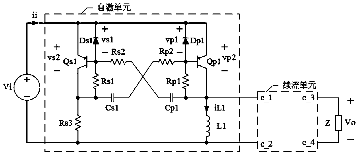
[0090] refer to Figure 2 to Figure 4 , a self-excited DC-DC converter with a switch on the input side, including a self-excited unit and a freewheeling unit, the self-excited unit includes resistors Rs2 to Rs3, resistor Rp2, capacitor Cs1, capacitor Cp1, diode Ds1, diode Dp1, inductor L1, PNP type BJT tube Qs1 and PNP type BJT tube Qp1, the freewheeling unit has ports c_1, port c_2, port c_3 and port c_4, and the function of the freewheeling unit is to act as a PNP type BJT When the tube Qp1 is cut off, it provides a current path for the inductor L1. The emitter of the PNP-type BJT tube Qs1 is simultaneously connected to the positive terminal of the DC power supply Vi, the cathode of the diode Ds1, the cathode of the diode Dp1 and the emitter of the PNP-type BJT tube Qp1, and the base of the PNP-type BJT tube Qs1 is simultaneously connected to the diode The anode of Ds1 is connected to one end of resistor Rs2, the collector of PNP type BJT tube Qs1 is connected to one end of...
Embodiment 2
[0099] refer to Figure 5 to Figure 7, a self-excited DC-DC converter with a switch on the input side. The self-excited unit includes a resistor Rs1 and a resistor Rp1. The resistor Rs1 and the resistor Rp1 are used as voltage limiting resistors. One end of the resistor Rs1 is connected to the other end of the capacitor Cs1. The resistor One end of Rp1 is connected to the other end of capacitor Cp1.
[0100] Other structures of embodiment 2 are the same as embodiment 1. The working process of embodiment 2 is also similar to embodiment 1 except that the function of Rs1 and Rp1 is to limit the terminal voltage of Cs1 and Cp1.
[0101] refer to Figure 8 , when the freewheeling module preferred scheme 1 is adopted, embodiment 2 essentially becomes a self-excited Buck-Boost converter. In the steady state, the polarity of the output voltage Vo of the embodiment 2 adopting the first preferred scheme of the freewheeling unit is opposite to Vi, and the size of Vo satisfies one of: ...
Embodiment 3
[0105] refer to Figure 17 to Figure 20 , a self-excited DC-DC converter with a switch on the input side, including a self-excited unit, an inductor L1 and a capacitor Co, the self-excited unit includes resistors Rs2 to Rs3, resistor Rp2, capacitor Cs1, capacitor Cp1, Diode Ds1, diode Dp1, diode D1, PNP type BJT transistor Qs1 and PNP type BJT transistor Qp1. The emitter of the PNP-type BJT tube Qs1 is simultaneously connected to the positive terminal of the DC power supply Vi, the cathode of the diode Ds1, the cathode of the diode Dp1 and the emitter of the PNP-type BJT tube Qp1, and the base of the PNP-type BJT tube Qs1 is simultaneously connected to the diode The anode of Ds1 is connected to one end of resistor Rs2, the collector of PNP type BJT tube Qs1 is connected to one end of resistor Rs3 and one end of capacitor Cs1 at the same time, the base of PNP type BJT tube Qp1 is connected to the anode of diode Dp1 and one end of resistor Rp2 at the same time The other end of ...
PUM
 Abstract
Description
Claims
Application Information
 - R&D Engineer
- R&D Manager
- IP Professional
- Industry Leading Data Capabilities
- Powerful AI technology
- Patent DNA Extraction
Browse by: Latest US Patents, China's latest patents, Technical Efficacy Thesaurus, Application Domain, Technology Topic, Popular Technical Reports.
© 2024 PatSnap. All rights reserved.Legal|Privacy policy|Modern Slavery Act Transparency Statement|Sitemap|About US| Contact US: help@patsnap.com