Multi-stage pore pipe weir shunting silting method

A technology of multi-level holes and hole tubes, applied in barrage/weirs, water conservancy projects, sea area projects, etc., can solve problems such as unfavorable embankment safety, embankment safety threats, flood floodplains, etc., and achieve high construction efficiency and stress-bearing conditions Good, wide range of sedimentation effect

Active Publication Date: 2019-05-21
YELLOW RIVER ENG CONSULTING
View PDF5 Cites 2 Cited by
  • Summary
  • Abstract
  • Description
  • Claims
  • Application Information

AI Technical Summary

Problems solved by technology

However, the phenomenon of "high trough, low beach, and depression at the root of embankment" appears in some sections of rivers with a lot of sediment, that is, Figure 7 The unfavorable shape of the "second-level suspended river" shown in the figure will easily lead to flooding in the middle and constant floods, and the formation of oblique rivers, horizontal rivers, and flooding along the embankment are unfavorable to the safety of the embankment during flood discharge.
In order to alleviate the threat to the safety of the embankment caused by the unfavorable shape of the "secondary suspended river", a protective dam was adopted on the river side of the embankment to deflect the flow away from the shore, but the low-lying terrain at the root of the embankment did not change

Method used


Image

  • Multi-stage pore pipe weir shunting silting method
  • Multi-stage pore pipe weir shunting silting method
  • Multi-stage pore pipe weir shunting silting method

Examples


Embodiment Construction

[0029] The embodiments of the present invention will be described in detail below in conjunction with the accompanying drawings. This embodiment is implemented on the premise of the technical solution of the present invention, and detailed implementation methods and specific operating procedures are provided, but the scope of protection of the present invention is not limited to the following Described embodiment.

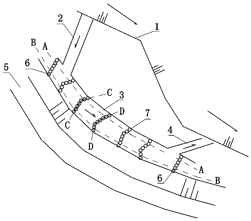
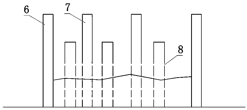
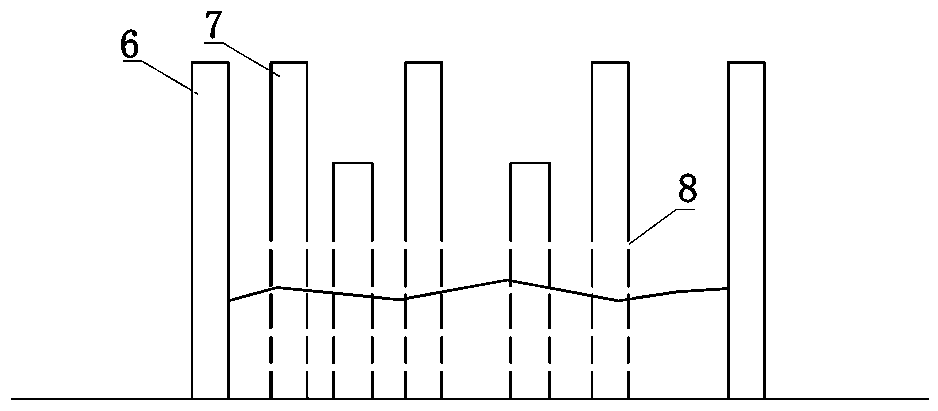
[0030] like Figure 1-6 Shown, the multi-stage hole tube weir diversion discharge method for silting of the present invention, comprises the following steps:

[0031] Step 1. Excavate the water diversion channel 2 upstream of the river main channel 1 where the silt should be released to the embankment root depression area 3. The angle between the axis of the water diversion channel 1 and the flow direction of the river main channel 1 is less than 45° and smoothly connected. The size of the excavation section is comprehensively determined by the determined water di...


PUM


Abstract

A multi-stage pore pipe weir shunting silting method comprises the following steps: 1, a water diversion channel is excavated in the upstream of a region to be silted of a river main tank to reach a dike root depression silt falling region, and an included angle between the axis of the water diversion channel and the water flow direction of the river main tank is an acute angle; 2, a drainage channel is excavated to the depression silt falling area of the embankment at the downstream of the to-be-silted area of the river main tank, and an included angle between the axis of the drainage channeland the water flow direction of the river main tank is an acute angle; 3, a plurality of rows of hole pipe weirs are arranged at intervals in the depression silt falling area of the embankment root along the direction of the embankment, wherein each row of hole pipe weirs are transversely arranged along the silt falling area of the embankment root; in the depression silt falling area of the embankment root, the hole pipe weirs located on the upstream side of the diversion channel and the downstream side of the drainage channel form a water-impermeable hole pipe weir through water-impermeablevertical pipes, the rest hole pipe weirs form a water-permeable hole pipe weir through water-permeable vertical pipes, and water passing holes are formed in the pipe walls of the upstream face and thedownstream face of each water-permeable vertical pipe. The low-lying area of the embankment root is raised through high-sand-content river water deposition, water is used for controlling water, and the purposes of preventing river downstream embankment from being endangered and preventing flood safety are achieved.

Description

technical field [0001] The invention relates to an outward drainage and silt discharge project of a silt-rich river in a water conservancy and hydropower project, in particular to a multi-stage hole pipe weir diversion and silt discharge method. Background technique [0002] The riverbeds of rivers with a lot of silt often have silt deposits. In order to ensure the safety of the river course, silt must be released to reinforce the embankment. Taking the Yellow River in my country as an example, the lower reaches of the Yellow River are world-famous suspended rivers above the ground. The bottom of the river is 3m to 9m above the ground on both sides. , "Xianhe" and "flooding along the embankment" often occur, which have brought great hidden dangers to the flood control of the Yellow River. [0003] In order to solve the sedimentation phenomenon on the riverbed, currently the main measures to strengthen the embankment are to discharge silt on the backwater side of the embankme...

Claims


Application Information

Patent Timeline
IPC IPC(8): E02B8/02E02B8/06
Inventor 苏东喜
Owner YELLOW RIVER ENG CONSULTING
Why Eureka
Try Eureka