
Steel wire strip longitudinal tear detection device

A technology of longitudinal tearing and detection device, applied in conveyor control device, transportation and packaging, conveyor and other directions, can solve the problems of longitudinal tearing, high cost, enterprise property loss, etc., to reduce the accident scale and use effect. Ideal, reduce property damage effect

Active Publication Date: 2019-05-14
牡丹江市北龙机械电力设备厂
View PDF8 Cites 0 Cited by
  • Summary
  • Abstract
  • Description
  • Claims
  • Application Information

AI Technical Summary

Problems solved by technology

[0002] Steel wire belt is a common equipment in the electric power, metallurgy, mining and port transportation industries. There are multiple steel strands inside along the transmission direction, so the longitudinal tensile capacity along the transmission direction is very strong, but it is also easy to Longitudinal tearing
The cost of the steel wire belt is very high. It can be said that it is the most expensive spare part in the belt transmission equipment. Once the longitudinal tear occurs, it is a vicious accident and will bring serious property losses to the enterprise.
Although the industries that currently use steel wire strips are equipped with detection devices for detecting longitudinal tearing of steel wire strips, the detection results are not accurate enough, the detection effect is not good enough, and the use effect is not ideal.

Method used


Image

  • Steel wire strip longitudinal tear detection device
  • Steel wire strip longitudinal tear detection device

Examples


Embodiment Construction

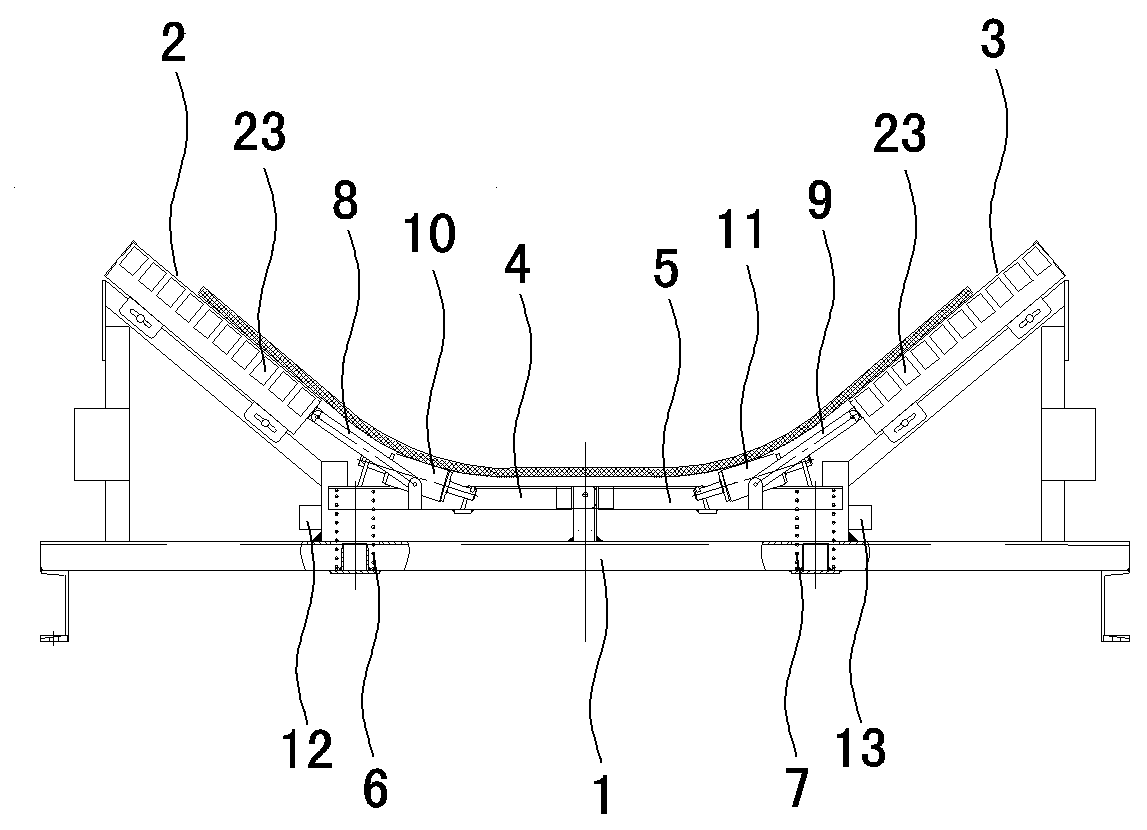
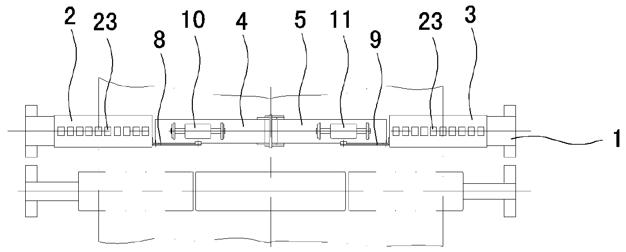
[0008] Such as figure 1 , figure 2 As shown, it comprises a device frame 1, the left and right sides of the device frame 1 are respectively provided with a left detector 2 and a right detector 3 for detecting the positions on both sides of the steel wire belt, and the left detector 2 and the right detector 3 are respectively connected with the two sides of the steel wire belt. The lower surface of the slope surface on the side matches and is installed on the device frame 1 along the axial sliding of the inclined rollers on both sides of the steel wire belt. The device frame 1 is located between the left detector 2 and the right detector 3. The left crossbeam 4 and the right crossbeam 5 below the steel wire belt, one end of the left crossbeam 4 and the right crossbeam 5 is respectively hinged on the middle part of the device frame 1 with the traveling direction of the steel wire tape as the hinge axis, and the other end is respectively towards the left side of the device frame...


PUM


Abstract

The invention relates to a steel wire strip longitudinal tear detection device.The steel wire strip longitudinal tear detection device comprises a device frame (1), a left detector (2) and a right detector (3) are separately arranged on the left side and the right side of the device frame, a left crossbeam (4) and a right crossbeam (5) are arranged at a position between the left detector and the right detector, and one ends of the left crossbeam and the right crossbeam are separately hinged to the middle of the device frame. A left reset pressure spring (6) is arranged between the left crossbeam and the device frame, a right reset pressure spring (7) is arranged between the right crossbeam and the device frame, a left connecting rod (8) is arranged between the left crossbeam and the left detector, and a right connecting rod (9) is arranged between the right crossbeam and the right detector. A left detection roller (10) is arranged on the left side of the left crossbeam, a right detection roller (11) is arranged on the right side of the right crossbeam, and a left detection switch (12) and a right detection switch (13) are separately arranged on the left side and the right side of the device frame. The steel wire strip longitudinal tear detection device can accurately detect whether a longitudinal tear condition exists in a steel strip or not, the detection effect is good, the application effect is ideal, and the property loss can be greatly reduced.

Description

technical field [0001] The invention relates to a detection device for conveying machinery, in particular to a detection device for longitudinal tearing of a steel wire belt. Background technique [0002] Steel wire belt is a common equipment in the electric power, metallurgy, mining and port transportation industries. There are multiple steel strands inside along the transmission direction, so the longitudinal tensile capacity along the transmission direction is very strong, but it is also easy to Longitudinal tearing occurs. The cost of the steel wire belt is very high. It can be said that it is the most expensive spare part in the belt transmission equipment. Once the longitudinal tear occurs, it is a malignant accident and will bring serious property losses to the enterprise. Although the industries using steel wire strips are equipped with detection devices for detecting longitudinal tearing of steel wire strips, the detection results are not accurate enough, the detec...

Claims


Application Information

Patent Timeline
Patent Type & Authority Applications(China)
IPC IPC(8): B65G43/00B65G15/48
Inventor 李运李德重杨傲杨志伟王亚涛易继远
Owner 牡丹江市北龙机械电力设备厂
Learn More