Flue gas washing method and catalytic cracking method
A washing method and flue gas technology, which is applied in catalytic cracking, cracking, separation methods, etc., can solve the problems of flue gas tailing, etc., and achieve the goals of slowing down equipment corrosion, simple and easy washing method, and reducing operating load and absorption liquid consumption Effect
- Summary
- Abstract
- Description
- Claims
- Application Information
AI Technical Summary
Problems solved by technology
Method used
Image


Examples
Embodiment 1
[0075] Add 1.5% by weight of the sulfur transfer agent prepared according to Example 5 of patent CN1323132C into the catalyst system of the catalytic cracking unit, and the regenerated flue gas enters the flue gas inlet of the washing tower after heat exchange by the waste heat boiler. The average composition of the main pollutants in the inlet flue gas is: SO 2 : 95mg / m 3 , SO 3 : 10mg / m 3 , NOx: 85mg / m 3 , solid dust: 115mg / m 3 . Flue gas flow 5100Nm 3 / min, the inlet temperature is 170°C.
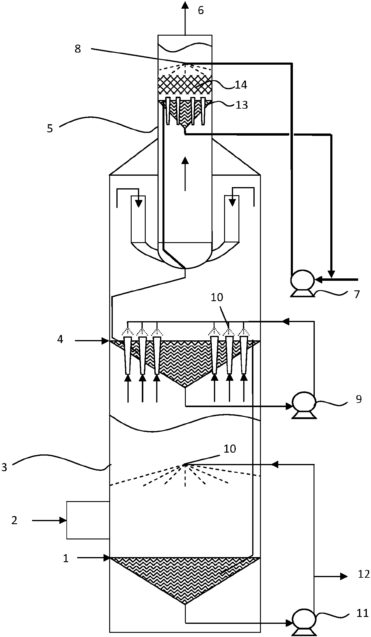
[0076] The structure of the washing tower is attached figure 1 As shown, a primary clean water spraying device is set in the chimney 5. The cleaning water nozzle 8 adopts a polytetrafluoro material spiral nozzle, the number is 4, and it is arranged at an angle of 90° along the circumferential direction, such as figure 2 shown. Honeycomb structured packing with a bed height of 0.3 m is filled between the clean water nozzle 8 and the clean water liquid storage tank 13 . The tem...
Embodiment 2
[0079] Add 1.8% by weight of the sulfur transfer agent prepared according to Example 5 of patent CN1323132C into the catalyst system of the catalytic cracking unit, and the regenerated flue gas enters the flue gas inlet of the washing tower after heat exchange in the waste heat boiler. The average composition of the main pollutants in the inlet flue gas is: SO 2 : 65mg / m 3 , SO 3 : 10mg / m 3 , NOx: 82mg / m 3 , solid dust: 124mg / m 3 . Flue gas flow 5100Nm 3 / min, the inlet temperature is 170°C.
[0080] The structure of the washing tower is different from that of Example 1 in that no clean water spraying device is installed in the chimney, but the absorption liquid feed valve of the second-stage absorption liquid spraying device in the washing tower body is closed, and it is directly converted to clean water spraying. That is, it is supplied with clean water instead of absorption fluid. The temperature of the fresh clean water provided to the clean water spraying device i...
Embodiment 3
[0083] The catalyst system of the catalytic cracking unit does not contain a sulfur transfer agent, and the regenerated flue gas enters the inlet of the scrubber after heat exchange in the waste heat boiler. The mean value of the main pollutant composition of the inlet flue gas is, SO 2 : 850mg / m 3 , SO 3 : 590mg / m 3 , NOx: 90mg / m 3 , solid dust: 120mg / m 3 . Flue gas flow 5100Nm 3 / min, the inlet temperature is 170°C.
[0084] The structure of the washing tower is the same as in Example 1. The temperature of the fresh clean water provided to the clean water spraying device is 20°C, the dissolved solid content is 0.002% by weight, and the replenishment amount is 5t / h (0.016kg / Nm 3 flue gas), cleaning water nozzle pump outlet pressure 0.4MPa, total spraying 0.12kg water / Nm 3The flue gas and clean water are directly sent to the clean water spray device (clean water nozzle) by the clean water supply pump 7, and the clean water collected by the clean water storage tank 13 ...
PUM
 Abstract
Description
Claims
Application Information
 - R&D
- Intellectual Property
- Life Sciences
- Materials
- Tech Scout
- Unparalleled Data Quality
- Higher Quality Content
- 60% Fewer Hallucinations
Browse by: Latest US Patents, China's latest patents, Technical Efficacy Thesaurus, Application Domain, Technology Topic, Popular Technical Reports.
© 2025 PatSnap. All rights reserved.Legal|Privacy policy|Modern Slavery Act Transparency Statement|Sitemap|About US| Contact US: help@patsnap.com