
Integrated curtain wall processing equipment

A processing equipment and curtain wall technology, which is applied in the field of curtain wall integrated processing equipment, can solve the problems of extended processing time, cumbersome operation, and low production efficiency, and achieve the effects of improving performance, product quality, and high positioning accuracy

Active Publication Date: 2019-05-07
安徽甫田幕墙材料有限公司
View PDF6 Cites 0 Cited by
  • Summary
  • Abstract
  • Description
  • Claims
  • Application Information

AI Technical Summary

Problems solved by technology

[0003] Due to the particularity of the structure and function of the curtain wall, it needs to be pre-embedded and punched to facilitate the connection with the wall. The existing punching device generally only uses relatively simple auxiliary tools for positioning and punching, and it needs to be drilled one by one. For processing, the operation is cumbersome and the production efficiency is low. The curtain wall after positioning and punching is then cut in different sizes according to different actual needs. At present, after the cutter on the workbench performs one side cutting work, it needs to be cut again to prolong the processing The time is not conducive to the use of the device. The processing equipment needs to perform multiple processing procedures such as drilling, grinding and fixing the structural parts. The existing processing is often the processing and installation of the structural parts alone, which wastes a lot of time. and production costs, reducing work efficiency

Method used


Image

  • Integrated curtain wall processing equipment
  • Integrated curtain wall processing equipment
  • Integrated curtain wall processing equipment

Examples


Embodiment Construction

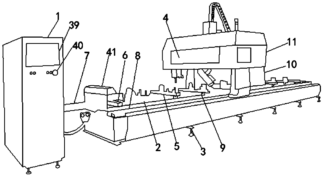
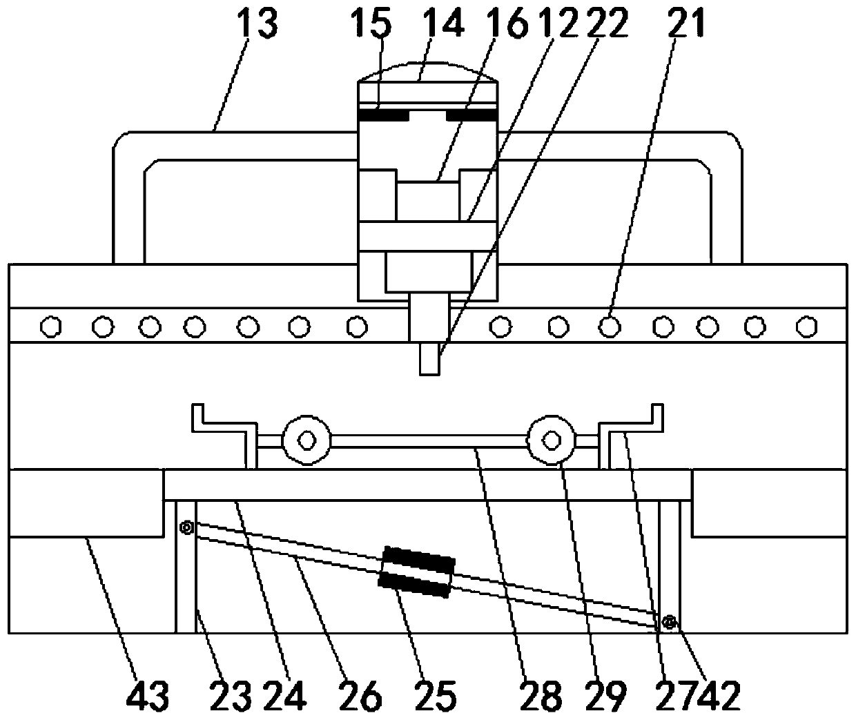
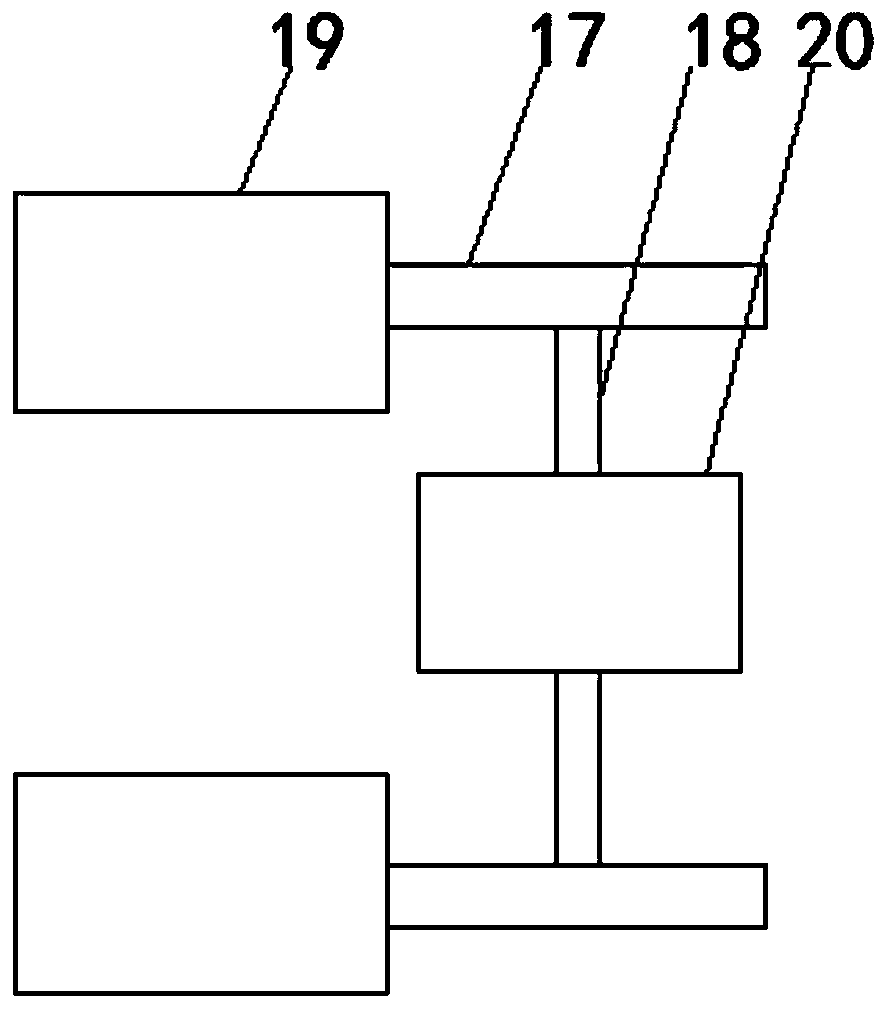
[0021] Refer to attached Figure 1-4 , an integrated curtain wall processing equipment, including a power cabinet 1, a workbench 2, a bracket 3, a machining center 4, a gantry saw 5, and a clamping part 6, and the power cabinet 1 is controlled and connected to the machining center 4 through a power line , the machining center 4 is located at the top of the workbench 2, one end of the workbench 2 is provided with the gantry saws 5 arranged equidistantly, and the bottom of the gantry saws 5 is connected to the clamping part 6 through a push rod 7 There are guide rails 8 fixedly connected between the clamping part 6 and the workbench 2, the guide rails 8 are located on both sides of the top of the workbench 2, and the top of the guide rails 8 is connected with The rotating shaft 9 of the workbench 2 is equipped with a fixing device 10 at the end far away from the gantry saw 5 .

[0022] The machining center 4 is externally placed in a cover body 11, the top center of the cover b...


PUM


Abstract

The invention relates to integrated curtain wall processing equipment which comprises an electric cabinet, a working table, a bracket, a processing center, gantry saws and clamping parts, wherein theelectric cabinet is in control connection with the processing center through a power line; the processing center is positioned at the top of the working table; the gantry saws are arranged at one endof the working table at equal intervals; the bottoms of the gantry saws are connected with the clamping parts through a push rod; the external part of the processing center is arranged in a cover body; a framework extending into the cover body is connected with the bottom of a spindle; a sliding block is arranged on the side, close to the inner wall of the cover body, of the framework; an X-axis rod and a Y-axis rod are connected with the two sides of the bottom end of the sliding block separately and are movably connected with a transverse auxiliary rod and a longitudinal auxiliary rod separately; the transverse auxiliary rod is fixedly connected with the bottom of the longitudinal auxiliary rod through rollers arranged at equal intervals; and processing heads connected with the spindle are arranged among the rollers. The integrated curtain wall processing equipment has the benefits of realizing integration of punching, peeling and grinding, fixing and packaging, being high in positioning precision, effectively improving the product quality and being suitable for popularization.

Description

technical field [0001] The invention relates to the technical field of curtain wall production and processing equipment, in particular to an integrated curtain wall processing equipment. Background technique [0002] Aluminum curtain wall is the outer wall enclosure of the building. It is not load-bearing and hangs up like a curtain, so it is also called "curtain wall". It is a light-weight wall with decorative effect commonly used in modern large-scale and high-rise buildings. Composed of panels and supporting structure systems, it can have a certain displacement capacity relative to the main structure or a certain deformation capacity itself, and does not bear the role of the main structure. The building envelope structure or decorative structure (the external wall frame support system is also a curtain wall system kind of). [0003] Due to the particularity of the structure and function of the curtain wall, it needs to be pre-embedded and punched to facilitate the connec...

Claims


Application Information

Patent Timeline
IPC IPC(8): B23P23/04
Inventor 刘正三
Owner 安徽甫田幕墙材料有限公司
Learn More