
Microfluidic chip with controllable tube side

A microfluidic chip and tube process technology, applied in laboratory containers, laboratory utensils, chemical instruments and methods, etc., can solve the problem of affecting experimental efficiency, difficult to control the precise reaction time of two material flows, and inconvenient reaction time. and other problems to achieve the effect of monitoring the control process

Active Publication Date: 2019-05-07
路煜恒
View PDF18 Cites 0 Cited by
  • Summary
  • Abstract
  • Description
  • Claims
  • Application Information

AI Technical Summary

Problems solved by technology

But at this time, the ideal confluent manifold has been obtained, that is, the ideal flow ratio of the two material flows, and it is inconvenient to control the reaction time by adjusting the parameters of the microflow pump.
If the tube length cannot be adjusted according to the needs, it is difficult to control the precise reaction time of the two-substance flow, which brings great limitations to the precise operation of microfluidics, especially in the control of fluid contact time.
In addition, the downstream micropipelines of the traditional microfluidic chip cannot be disassembled, and it is difficult or takes a lot of time to clean up after being blocked by samples, reaction products or impurities, which greatly affects the efficiency of the experiment

Method used


Image

  • Microfluidic chip with controllable tube side
  • Microfluidic chip with controllable tube side
  • Microfluidic chip with controllable tube side

Examples


Embodiment approach

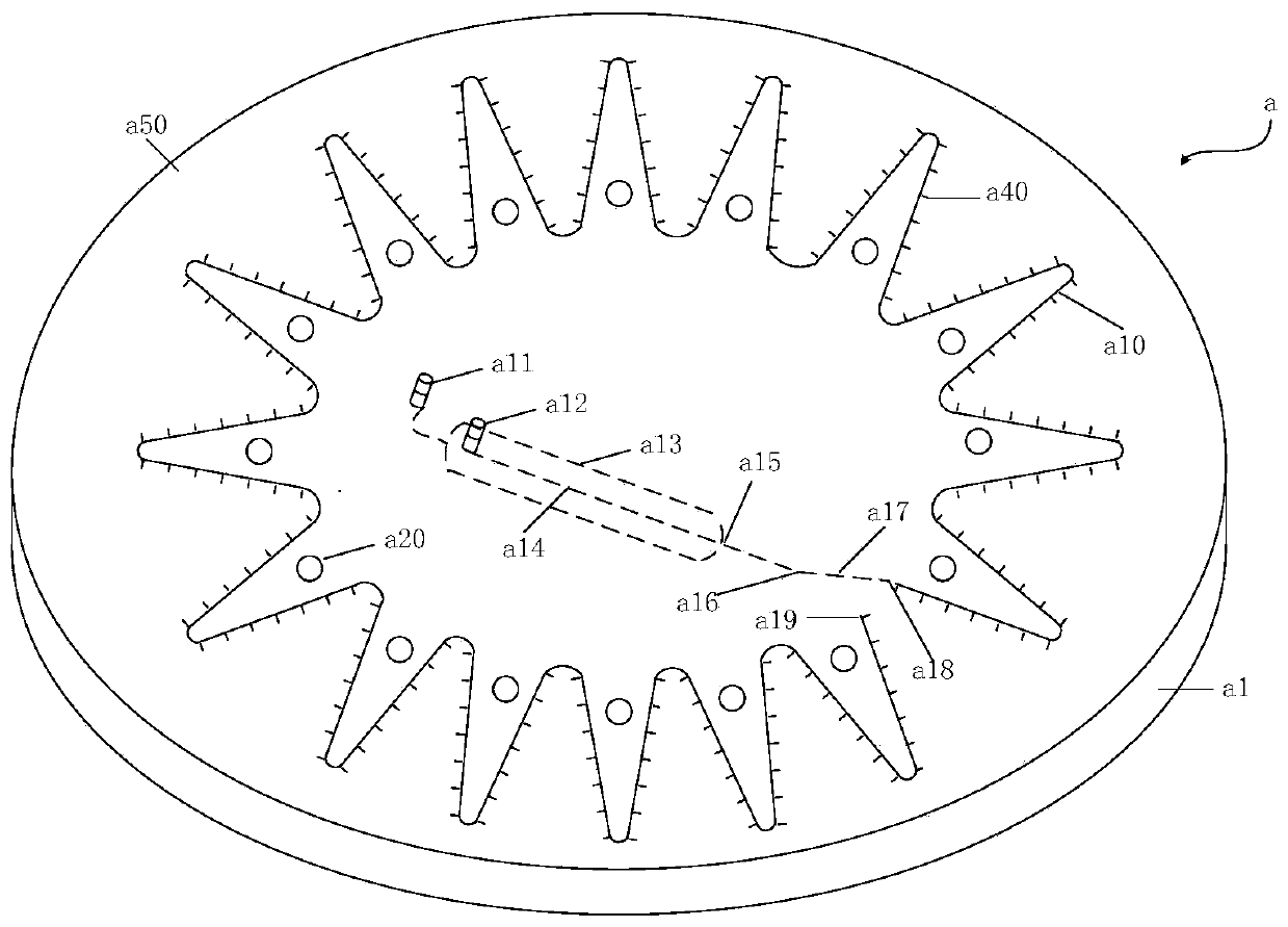
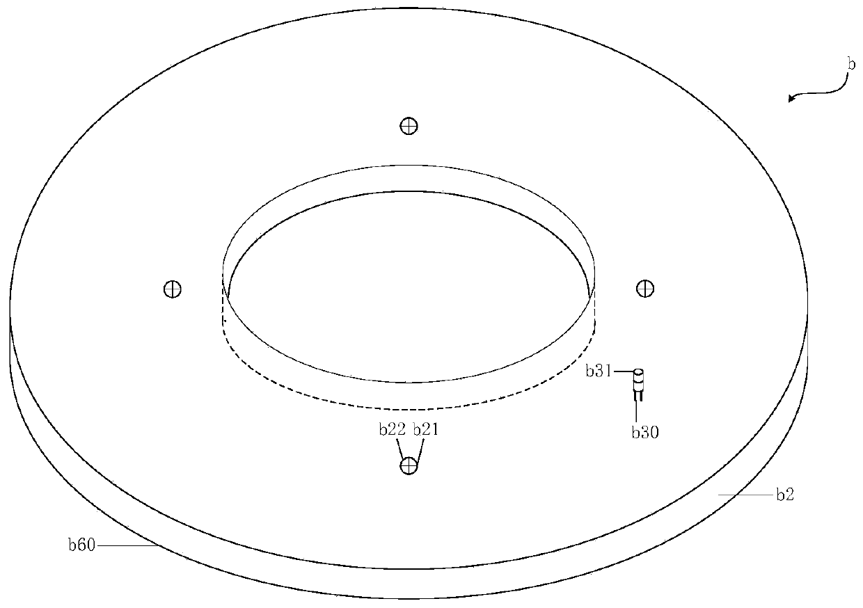
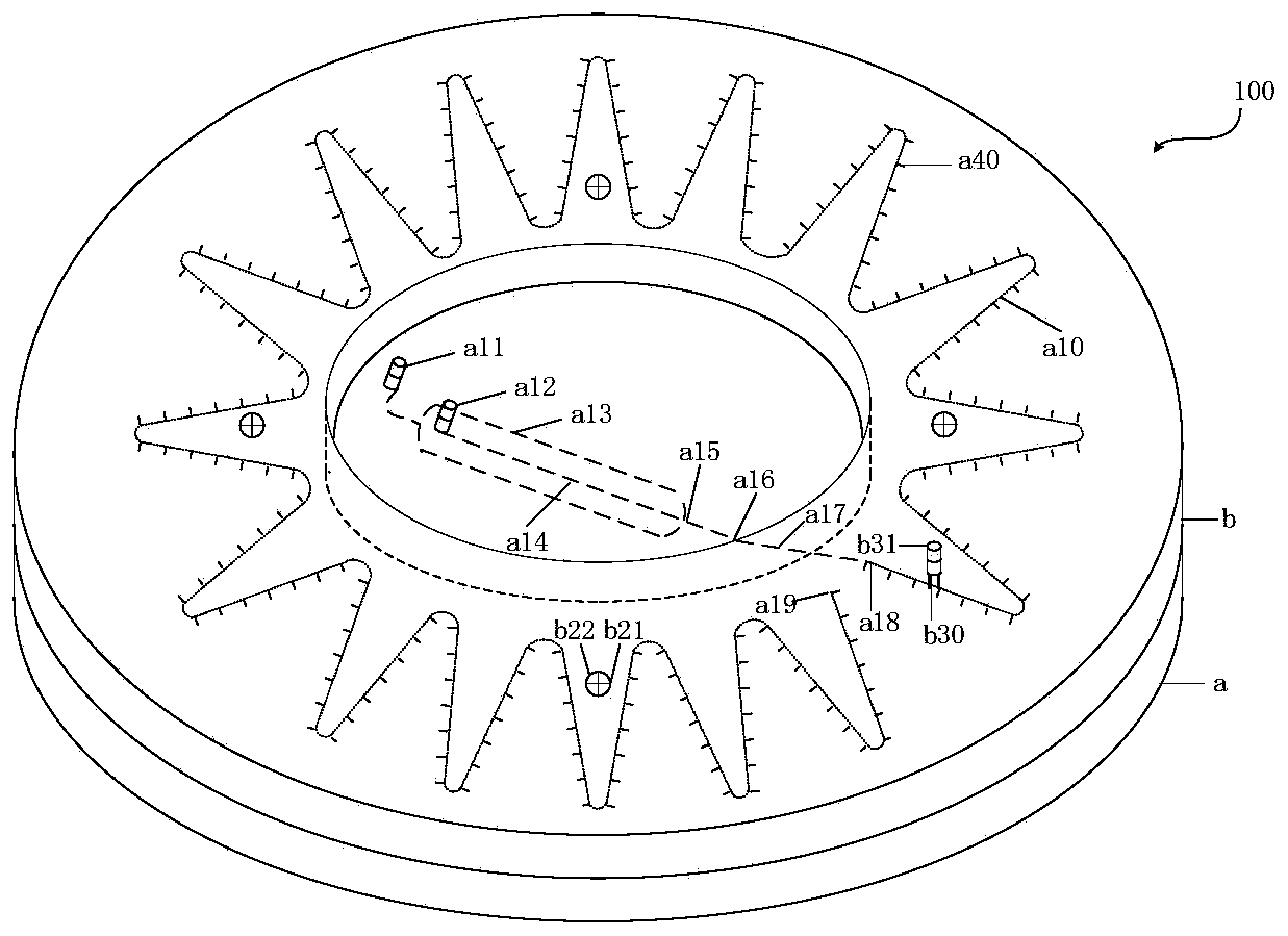
[0096] In some specific embodiments of the present invention, the micropipe grooves are a circular substrate with corrugated distribution such as figure 1 shown. figure 1 Among them, the circular substrate a in which the microtube recesses are distributed in a corrugated shape includes a substrate a1, and a microtube recess used as a closed end a19 of the microtube reactor is arranged in the annular region of the substrate a1 corresponding to the annular cover plate b Road a10, the cross-section of the micropipe groove a10 is C-shaped or rectangular with the opening upward and flush with the upper surface a50 of the base a1; At least 16 screw holes a20 are uniformly and symmetrically distributed on the circumference, and the screw holes a20 have a screw hole depth equal to 1 / 3-2 / 3 of the thickness of the substrate a1, or the screw holes a20 are through channels.

[0097] A sealing strip groove a70 is provided on both sides and ends of the micropipe groove a10, and the sealing...


PUM


Abstract

The invention relates to a microfluidic chip with a controllable tube side. The microfluidic chip comprises a circular substrate and an annular cover plate capable of being tightly bonded to the uppersurface of the circular substrate; and the interior of the part, corresponding to the annular region of the annular cover plate, of the circular substrate is provided with microtube concave channelswhich have upward openings and closed tail ends and are flush with the upper surface of the circular substrate, the annular cover plate is provided with openings for adjusting the microtube tube sidesin the directions of the microtube concave channels, each opening is connected with one corresponding material outlet of a microtube reactor. The microfluidic chip provided by the invention can directly adjust tube side lengths in real time according to the reaction time and flow rate of the required reaction or detection operation, thereby achieving the purpose of accurately controlling the contact and reaction time of two fluids.

Description

technical field [0001] The invention belongs to the technical field of microfluidic chips, and relates to a microfluidic chip with controllable tube length, in particular to a microfluidic chip capable of controlling the contact and reaction time of different fluids in the chip by controlling the tube length of micropipes . Background technique [0002] A microfluidic chip is a miniaturized, integrated chip with micron-scale channels. The main materials for making microfluidic chips include various silicon wafers, quartz, glass, polymer materials, elastic materials, and metals, etc., and their manufacturing technologies have matured. The fluid behavior and fluid characteristics in the microchannel of the microfluidic chip are different from those in the macroscopic channel. Due to the high resistance of fluid flow in the micro-nano-scale channel, the liquid-solid, liquid-gas, The interfacial tension between the liquid-liquid phase plays a dominant role, and its two main fl...

Claims


Application Information

Patent Timeline
IPC IPC(8): B01L3/00
Inventor 路煜恒辛晨
Owner 路煜恒
Learn More