
Partial discharge detection system

A partial discharge detection and single-core cable technology, applied in the direction of testing dielectric strength, etc., can solve the problems of inability to accurately detect partial discharge of cable joints and the influence of complex electromagnetic environments, and achieve the goal of avoiding the detection of partial discharge signals in complex electromagnetic environments Interference, overcoming the influence of complex electromagnetic environment, and improving the effect of sensitivity

Pending Publication Date: 2019-05-03
SHENZHEN POWER SUPPLY BUREAU
View PDF0 Cites 5 Cited by
  • Summary
  • Abstract
  • Description
  • Claims
  • Application Information

AI Technical Summary

Problems solved by technology

[0004] Based on this, it is necessary to provide a partial discharge detection system to solve the problem that the partial discharge monitoring equipment in the related art is easily affected by the complex electromagnetic environment and cannot accurately detect the partial discharge of all cable joints

Method used


Image

  • Partial discharge detection system
  • Partial discharge detection system
  • Partial discharge detection system

Examples


Embodiment Construction

[0082] In order to make the above-mentioned purpose, features and advantages of the present application more obvious and understandable, the specific implementation manners of the present application will be described in detail below in conjunction with the accompanying drawings. In the following description, numerous specific details are set forth in order to provide a thorough understanding of the application. However, the present application can be implemented in many other ways different from those described here, and those skilled in the art can make similar improvements without departing from the connotation of the present application. Therefore, the present application is not limited by the specific implementation disclosed below.

[0083] It should be noted that when an element is referred to as being “fixed” to another element, it can be directly on the other element or there can also be an intervening element. When an element is referred to as being "connected to" an...


PUM


Abstract

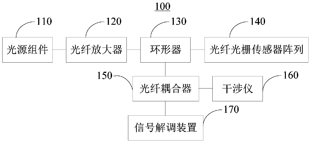
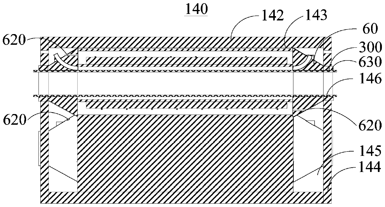
The invention relates to a partial discharge detection system which comprises a light source assembly, an optical fiber amplifier, a circulator, a fiber grating sensor array, a fiber coupler, an interferometer and a signal demodulating device. The partial discharge detection system can effectively avoid the interference of a complex electromagnetic environment to partial discharge signal detectionby adopting the passive components such as the fiber grating sensor array, the fiber coupler and the interferometer, so as to accurately detect the partial discharge condition of a cable joint. The fiber grating sensor array can simultaneously carry out partial discharge detection on each single core cable in a multi-core cable. A reflected pulse signal is modulated by the interferometer and interferes in the fiber coupler. An original signal carrying partial discharge information can be demodulated by the signal demodulating device. The sensitivity of the system is effectively improved. Thepartial discharge detection system can accurately detect the partial discharge of all cable joints in the complex electromagnetic environment.

Description

technical field [0001] The present application relates to the technical field of partial discharge detection, in particular to a partial discharge detection system. Background technique [0002] At present, most cross-linked vinyl cables in the distribution network adopt direct burial, cable trench, tunnel and other laying methods. Under the influence of comprehensive factors such as complex environment and high load, the cable will fail due to partial discharge due to insulation aging, process defects and other reasons. At the same time, most of the cable partial discharge occurs in the middle joint of the cable. However, the special environment of the cable intermediate joint makes it difficult for the staff to locate or repair the fault. [0003] In addition, unlike larger power equipment such as transformers and switch cabinets, cable joints have the characteristics of complex location and environment, large number and small size. Therefore, the partial discharge moni...

Claims


Application Information

Patent Timeline
Patent Type & Authority Applications(China)
IPC IPC(8): G01R31/12
Inventor 韦盈释陈金锋皮昊书陈子涵吴中宋书生周伟文杜浩夏金凯
Owner SHENZHEN POWER SUPPLY BUREAU
Learn More