Pneumatic buffering device and method

A technology of buffer device and air supply device, applied in vibration suppression adjustment, spring/shock absorber, mechanical equipment, etc., can solve the problems of reducing production efficiency, low buffer efficiency, increasing energy consumption and working time of feeding device, etc. The effect of improving buffer efficiency, improving adaptability, and improving buffer operation efficiency

Pending Publication Date: 2019-05-03
DALIAN FIELD HEAVY MACHINERY MFG CO LTD
View PDF10 Cites 1 Cited by
  • Summary
  • Abstract
  • Description
  • Claims
  • Application Information

AI Technical Summary

Problems solved by technology

This method will not only increase the energy consumption and working time of the feeding device, but also reduce the production efficiency
[0005] In addition, the constant setting of the moving speed of the piston rod of the existing pneumatic buffer device
If the moving speed of the piston rod is set to be fast, when buffering the material with large mass, the impact of the material on the pneumatic buffer device will be great; but if the moving speed of the piston rod is set to be slow, when the buffer mass is large For small materials, the buffer efficiency is low

Method used


Image

  • Pneumatic buffering device and method
  • Pneumatic buffering device and method
  • Pneumatic buffering device and method

Examples


Embodiment Construction

[0045] The present invention will be described in detail below in conjunction with the accompanying drawings and embodiments. It should be understood that the described specific embodiments are only used to explain the present invention, not to limit the present invention. Terms such as first, second, etc. in the text are only used to distinguish one entity (or operation) from another entity (or operation), and do not indicate any relationship or order between these entities (or operations); in addition, Terms such as up, down, left, right, front, back, etc. indicating directions or orientations in the text only indicate relative directions or orientations, rather than absolute directions or orientations. Without additional limitations, an element defined by a statement "comprising" does not exclude the presence of other elements in the process, method, article, or device that includes the element.

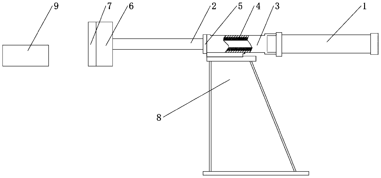
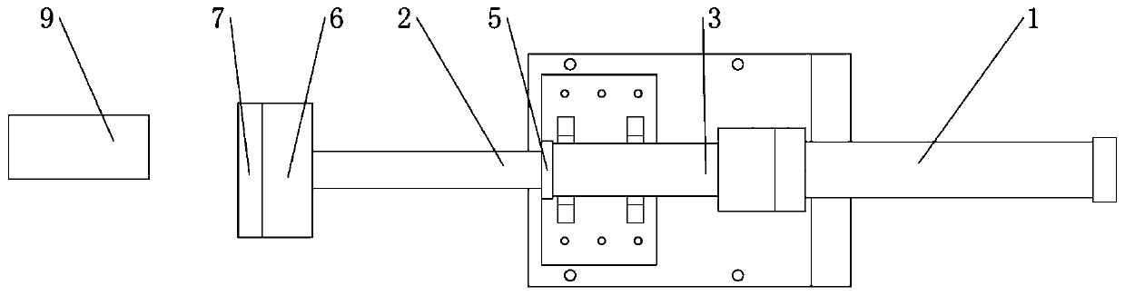
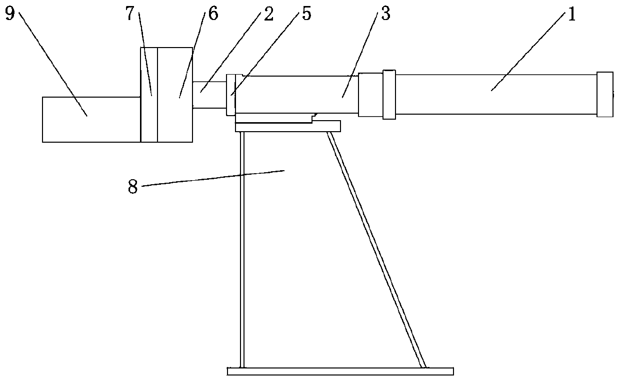
[0046] figure 1 It shows a schematic diagram of the mechanical structure of...


PUM


Abstract

The invention discloses a pneumatic buffering device and a control method. The pneumatic buffering device comprises a cylinder, a supporting base and a control device, wherein the cylinder comprises acylinder body and a piston rod; the supporting base is arranged on the side corresponding to the first end of the cylinder body, and the first end of the cylinder body is provided with a rod cavity of the cylinder body; the supporting base is provided with a supporting hole, and the supporting hole and the piston rod are coaxially arranged; the piston rod is partially arranged in the supporting hole and is in sliding connection with the supporting hole; the control device is used for detecting the air pressure intensity of the cylinder body and the position information of the piston rod, andadjusting the moving direction and the moving speed of movement of the piston rod along the supporting hole according to the air pressure intensity and the position information. Due to the pneumatic buffering device and the control method, the pneumatic buffering device can bear the bending torque, the moving speed of the piston rod can be adjusted according to different kinetic energy of materials, so that the pneumatic buffering device adapts to materials in different sizes, at different falling points and with different kinetic energy, and the overall efficiency of the pneumatic buffering device is improved.

Description

technical field [0001] The embodiment of the present invention relates to the technical field of transportation equipment, in particular to a pneumatic buffer device and method. Background technique [0002] When the horizontal pneumatic buffer device is running, if the feeding device does not adjust the height of the material, when the size of the material is different, because the height of the center of mass of the material is different, the impact point on the piston rod is different. When the impact point deviates from the center of the piston rod , the piston rod will experience a bending moment. When the vertical pneumatic buffer device is in operation, if the position of the material falling point is uneven, the piston rod will also be subjected to a bending moment. [0003] Under normal circumstances, the cylinder is not allowed to bear the bending moment, because after the piston rod is subject to the bending moment, the piston rod is easily deformed, and an offse...

Claims


Application Information

Patent Timeline
Patent Type & Authority Applications(China)
IPC IPC(8): F16F15/023
Inventor 高国武
Owner DALIAN FIELD HEAVY MACHINERY MFG CO LTD
Why Eureka
Try Eureka