
Novel composite insulator and production process thereof

A composite insulator, a new type of technology, applied in the production process of composite insulators and the field of new composite insulators, can solve the problems of easy to be broken by strong wind, weak interface bonding, poor product insulation, etc., to reduce the risk of use and operation. , The bonding is firm, and the effect of reducing the point of the interface

Inactive Publication Date: 2019-04-30
DONGGUAN GAONENG IND CO LTD
View PDF4 Cites 1 Cited by
  • Summary
  • Abstract
  • Description
  • Claims
  • Application Information

AI Technical Summary

Problems solved by technology

The disadvantages of this process are: when the overall injection molding is performed, the injection machine needs a very large injection pressure to fill the mold cavity with silicone rubber. When the silicone rubber flows under high pressure in the mold cavity, the primer on the surface of the mandrel metal fittings will be washed away, resulting in interface bonding. Not strong, easy to cause poor insulation inside the product
The obvious disadvantages of this process product are: first, the material for bonding the shed and the silicone rubber sheath is room temperature vulcanized silicone rubber, and room temperature vulcanized silicone rubber is different from heat vulcanized silicone rubber in terms of mechanical properties, electrical properties and aging properties. There is a huge gap; second, the room temperature vulcanized silicone rubber is used to bond the shed and the sheath, which adds two layers of connection interface to the product; Afterwards, it is easy to fall, and it is easy to be broken by strong wind in the wind area; fourth, because the sheaths are inserted into the sheath one by one, the connection between each sheds leaves interfaces on the insulating surface. Each interface is a hidden danger buried in the insulator

Method used


Image

  • Novel composite insulator and production process thereof

Examples


Embodiment Construction

[0013] The present invention is further described in conjunction with the following examples.

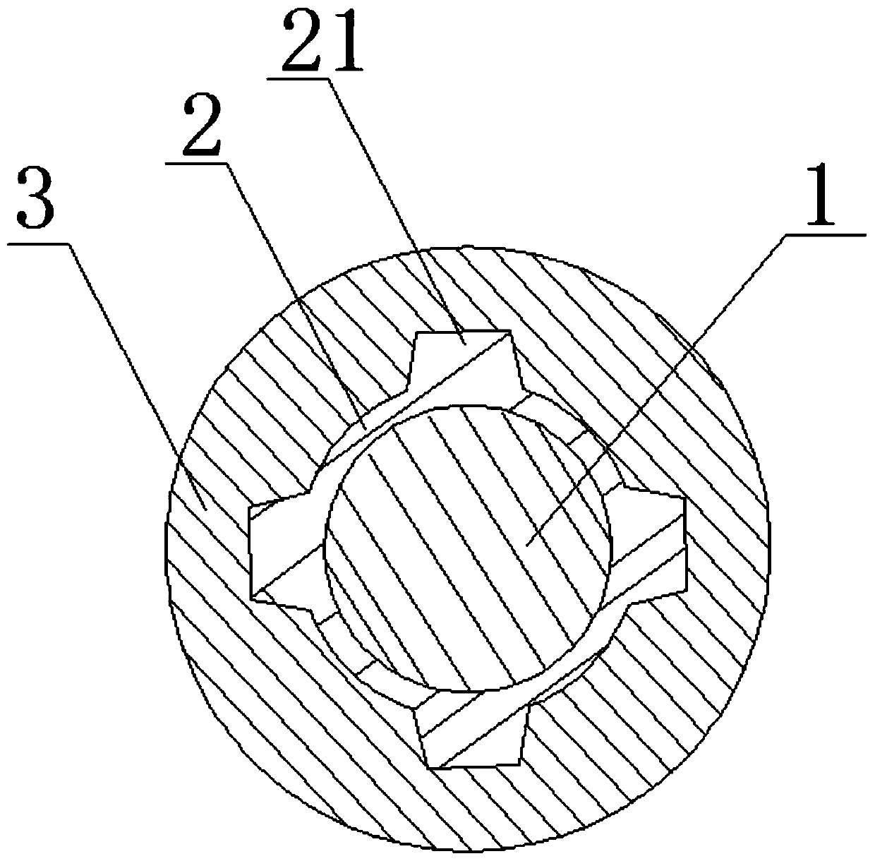
[0014] A specific embodiment of a novel composite insulator of the present invention, such as figure 1 As shown, it includes a mandrel 1, a silicone rubber sheath 2 and an umbrella skirt 3, the silicone rubber sheath 2 is fixedly sleeved on the outer surface of the mandrel 1 by extrusion, and the silicone rubber sheath 2 includes a sheath The body, the outer surface of the sheath body has four protruding lines 21 extending in a cross shape, and the shed 3 is molded on the outer surface of the silicone rubber sheath 2 by injection.

[0015] In the new composite insulator of this embodiment, compared with the prior art, the silicone rubber sheath 2 is fixed on the outer surface of the mandrel 1 by extrusion, and the shed 3 is fixed on the outer surface of the silicone rubber sheath 2 by injection. The outer surface, so that the bonding between the silicone rubber sheath 2 and the man...


PUM


Abstract

The invention relates to the technical field of composite insulators, in particular to a novel composite insulator and a production process thereof. The novel composite insulator includes a mandrel, asilicone rubber sheath and an umbrella skirt. The silicone rubber sheath fixedly sleeves the outer surface of the mandrel by extrusion. The silicone rubber sheath includes a sheath body, and four raised strips extend from the outer surface of the sheath body in the form of a cross. The umbrella skirt is formed on the outer surface of the silicone rubber sheath by injection. Compared with the prior art, the silicone rubber sheath is fixed on the outer surface of the mandrel by extrusion, and the umbrella skirt is fixed on the outer surface of the silicone rubber sheath by injection, so that the bonding between the silicone rubber sheath and the mandrel is firmer and more aging-resistant; and multiple interface generation points are reduced, so that moisture, acid and alkali are prevented from infiltrating into the mandrel, and the use and operation risk of the product is greatly reduced. The application also provides a production process of the composite insulator.

Description

technical field [0001] The invention relates to the technical field of composite insulators, in particular to a novel composite insulator, and also to a production process of the composite insulator. Background technique [0002] Organic composite insulators, as a major electrical component in power grid operation, play an important role in power transmission and electrified railway construction. The existing organic composite insulation production, a total of two processes. One is the overall injection molding process, and the other is the extrusion sheathing and stringing umbrella process. These two processes have their own insurmountable shortcomings in the production of organic composite insulators [0003] The overall injection molding process is to apply a layer of primer (silicone rubber coupling agent) on the surface of the organic composite insulator skeleton material mandrel and connecting hardware, and then inject the insulator shed sheath in a rubber injection m...

Claims


Application Information

Patent Timeline
Patent Type & Authority Applications(China)
IPC IPC(8): H01B17/04H01B17/38H01B19/00
CPCH01B17/04H01B17/38H01B19/00
Inventor 许文荣陈文杰何庆文惠强明安惠杨皓然袁少钧朱剑波张伟安方斌赵天任黄肖霞
Owner DONGGUAN GAONENG IND CO LTD
Learn More