
A fabric dyeing vat with cleaning device

A fabric dyeing and cleaning device technology, which is applied in the field of fabric dyeing vats, can solve problems such as troublesome maintenance, damage to workers' health, and damage to the ecological environment of water bodies, and achieve the effect of convenient post-processing and convenient and fast discharge

Active Publication Date: 2019-10-25
嘉兴市东亮染整有限公司
View PDF4 Cites 0 Cited by
  • Summary
  • Abstract
  • Description
  • Claims
  • Application Information

AI Technical Summary

Problems solved by technology

[0002] The production wastewater in the dye production industry has become one of the main pollution sources of water bodies, and because most dyes are toxic and refractory organic substances, their chemical stability is strong, and they have the "three effects" of carcinogenicity, teratogenicity, and mutagenicity. Therefore, in wastewater Even if the concentration of residual organic matter is very low, it will cause irreversible damage to the ecological environment of the water body. The traditional dyeing device must use excessive dyes for the dyeing effect. Once the dyeing is completed, the excess dyes will become waste water and need to be cleaned manually. The fabric dyeing vat has a low degree of automation and cannot be cleaned automatically. It needs to be cleaned manually. During the cleaning process, workers will inevitably come into contact with dyes, which will damage the health of workers. Secondly, during the long-term dyeing process, the dye itself is easy to accumulate impurities and affect the quality of the finished fabric. Quality, the traditional dyeing tank is not easy to clean, and the waste liquid in the cleaning process cannot be stored, which is very troublesome in the maintenance process, so it is necessary to design a fabric dyeing tank with a cleaning device

Method used

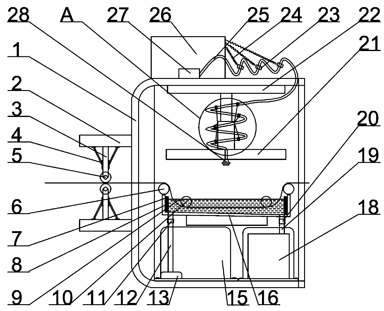

Image

  • A fabric dyeing vat with cleaning device
  • A fabric dyeing vat with cleaning device
  • A fabric dyeing vat with cleaning device

Examples


Embodiment Construction

[0022] The following will clearly and completely describe the technical solutions in the embodiments of the present invention with reference to the drawings in the embodiments of the present invention.

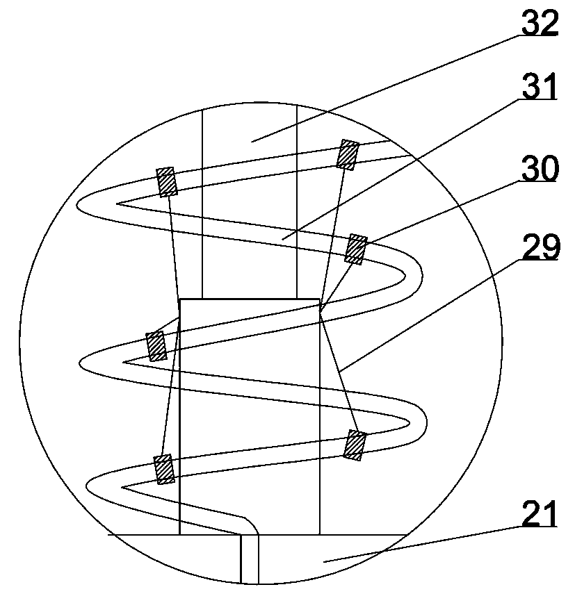
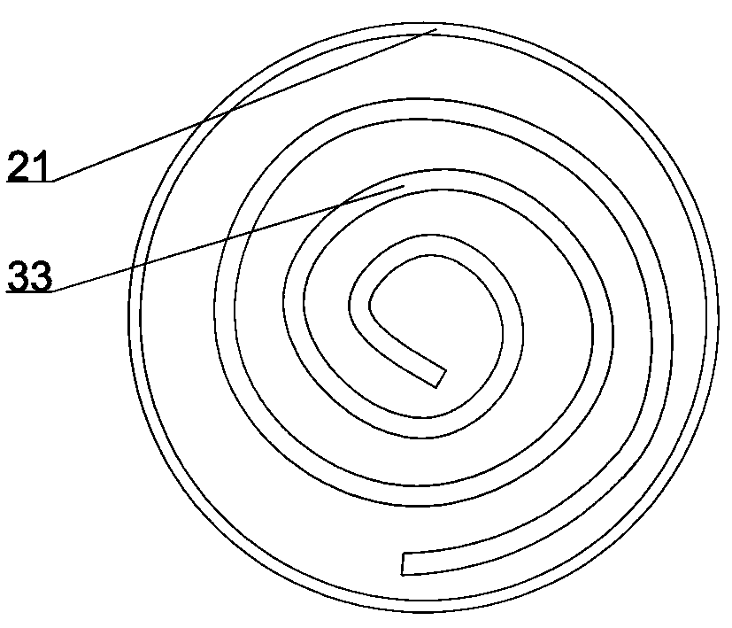
[0023] like Figure 1-7 As shown, the present invention provides a technical solution: a fabric dyeing vat with a cleaning device, comprising a device body 1, a water tank 26 is arranged above the top plate of the device body 1, a dye tank 7 is arranged in the middle of the device body 1, and the dye tank 7. A dye box 15 is arranged on the left side of the lower part, and a waste liquid box 18 is arranged on the right side of the dye box 15. A first fixing plate 2 is arranged on the left side of the left side plate of the device body 1, and two first fixing plates 2 are arranged. The first fixed rod 3 is arranged below the first fixed plate 2 on the upper side, the first support rod 4 is arranged on both sides of the first fixed rod 3, the rolling roller 5 is arranged on the l...


PUM


Abstract

The invention discloses a fabric dyeing jar with a cleaning device. The fabric dyeing jar with the cleaning device comprises a device body, a water tank, a nozzle, a dye tank, a dye box and a waste liquor tank, wherein a second water pump is arranged in the water tank; water in the water tank is sprayed out by the nozzle and then conveyed into an elastic bag by virtue of a liquid pipe; rotation ofthe gear is controlled by a third motor, a meshed external gear is driven by a gear, a rotating disc rotates by the external gear, and a second water inlet hole in the rotating disc is communicated with a first water inlet hole, so that the water is ejected from a lower nozzle, the dye tank is cleaned, the fabric is dyed by the dye tank, the dyes in the dye tank are supplemented by dyes stored inthe dye box, the used waste liquor is filtered and stored by the waste liquor tank, and the problems that lots of impurities are easily produced due to long-term use of the traditional dye tank, thedye tank is difficult to clean and cannot be automatically cleaned and the quality of the fabric is influenced due to long-term use can be solved.

Description

technical field [0001] The invention relates to the technical field of cloth processing equipment, in particular to a fabric dyeing vat with a cleaning device. Background technique [0002] The production wastewater in the dye production industry has become one of the main pollution sources of water bodies, and because most dyes are toxic and refractory organic substances, their chemical stability is strong, and they have the "three effects" of carcinogenicity, teratogenicity, and mutagenicity. Therefore, in wastewater Even if the concentration of residual organic matter is very low, it will cause irreversible damage to the ecological environment of the water body. The traditional dyeing device must use excessive dyes for the dyeing effect. Once the dyeing is completed, the excess dyes will become waste water and need to be cleaned manually. The fabric dyeing vat has a low degree of automation and cannot be cleaned automatically. It needs to be cleaned manually. During the c...

Claims


Application Information

Patent Timeline
Patent Type & Authority Patents(China)
IPC IPC(8): D06B3/10D06B23/20D06B23/30
CPCD06B3/10D06B23/20D06B23/30
Inventor 冯超王法胜冯丽娜
Owner 嘉兴市东亮染整有限公司
Learn More