
Continuous gas heating device

A gas heating device and gas technology, applied in the direction of air heaters, fluid heaters, lighting and heating equipment, etc., can solve the problems of complex operation of equipment, limited heating range, large equipment investment, etc., to achieve extended heating path, heat preservation Good effect, good heating effect

Inactive Publication Date: 2019-04-23
TIANJIN HUASAIER GAS
View PDF6 Cites 6 Cited by
  • Summary
  • Abstract
  • Description
  • Claims
  • Application Information

AI Technical Summary

Problems solved by technology

[0003] Existing gas heating devices generally use heating equipment fixed in the system and transported by heat-insulating pipelines. Such equipment investment is too large, equipment operation is complicated, the floor area is large, the cost is high, and the temperature of the outlet gas is unstable; Directly use the electric heater to connect to the system, so the range of temperature rise is very limited, the heating temperature is not high, the highest can only reach about 40-50 ℃, for pipeline drying or adsorbent activation, or equipment heating, or part of the reaction When using gas, the desired effect is often not obtained

Method used


Image

  • Continuous gas heating device
  • Continuous gas heating device

Examples


Embodiment Construction

[0016] The following will clearly and completely describe the technical solutions in the embodiments of the present invention with reference to the accompanying drawings in the embodiments of the present invention. Obviously, the described embodiments are only some, not all, embodiments of the present invention. Based on the embodiments of the present invention, all other embodiments obtained by persons of ordinary skill in the art without making creative efforts belong to the protection scope of the present invention.

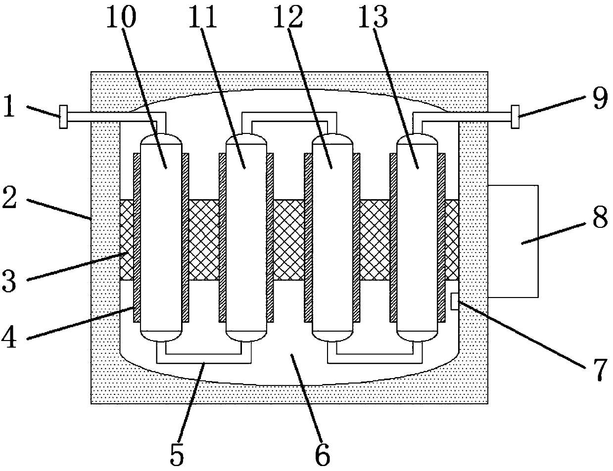
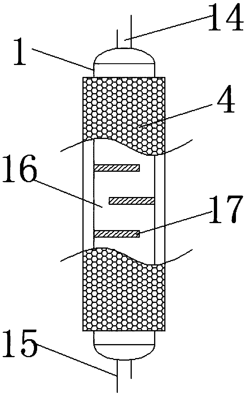
[0017] see Figure 1~2 , in an embodiment of the present invention, a continuous gas heating device, comprising an insulated box 2, a first heating cylinder 10, a second heating cylinder 11, a third heating cylinder 12 and a fourth heating cylinder 13, the insulated box 2. There is a heating chamber 6 inside, and an electric heating grid 3 is installed in the middle of the heating chamber 6. The heat conducting sleeve 4 is fixedly connected to the electric hea...


PUM


Abstract

The invention discloses a continuous gas heating device which comprises an insulating box body, a first heating barrel, a second heating barrel, a third heating barrel and a fourth heating barrel. A heating room is arranged in the insulating box body, an electric heating net is mounted in the middle of the heating room, the electric heating net is fixedly connected to heat conducting sleeves, theat least four heat conducting sleeves are uniformly distributed on the electric heating net, and the first heating barrel, the second heating barrel, the third heating barrel and the fourth heating barrel are separately arranged in the heat conducting sleeves in a sleeved manner. By conducting heat generated by the electric heating net to the heating barrels uniformly, gas successively flows through the first, second, third and fourth heating barrels, and an S-shaped heating channel is formed in the first heating barrel by means of a plurality of baffle fins, so that the heated path of gas inthe first heating barrel is prolonged, the heating effect is good, and continuous heating of gas is achieved.

Description

technical field [0001] The invention relates to the technical field of gas heating, in particular to a continuous gas heating device. Background technique [0002] In the gas industry, it is often necessary to heat up the gas, either to directly participate in the reaction, or as a dry gas, or to activate the adsorbent agent, or to heat the equipment as a medium. [0003] Existing gas heating devices generally use heating equipment fixed in the system and transported by heat-insulating pipelines. Such equipment investment is too large, equipment operation is complicated, the floor area is large, the cost is high, and the temperature of the outlet gas is unstable; Directly use the electric heater to connect to the system, so the range of temperature rise is very limited, the heating temperature is not high, the highest can only reach about 40-50 ℃, for pipeline drying or adsorbent activation, or equipment heating, or part of the reaction When using gas, the desired effect is...

Claims


Application Information

Patent Timeline
Patent Type & Authority Applications(China)
IPC IPC(8): F24H3/00F24H9/18F24H9/00F24H9/20
CPCF24H3/002F24H9/0063F24H9/1863F24H9/2071F24H2250/02
Inventor 宋亮
Owner TIANJIN HUASAIER GAS
Learn More