Low-frequency ultrasonic electrostatic atomizing nozzle

An atomizing nozzle, electrostatic type technology, applied in the field of low-frequency ultrasonic electrostatic atomizing nozzle, can solve the problems of small spray volume, large droplet size, small atomization volume, etc., and achieve the effect of increasing adhesion

Active Publication Date: 2019-04-23
黑龙江省北为智能科技有限责任公司
View PDF8 Cites 8 Cited by
  • Summary
  • Abstract
  • Description
  • Claims
  • Application Information

AI Technical Summary

Problems solved by technology

[0002] At present, the atomizing nozzles used in the field of atomizing cultivation are mainly piezoelectric ultrasonic atomizing nozzles and mechanical atomizing nozzles. The piezoelectric atomizing nozzles have a small spray volume and are only suitable for small-scale cultivation; while ordinary mechanical atomizing nozzles Although the amount of atomization is large, the particle size of the droplets produced by it is relatively large (greater than 100 μm) and the uniformity is poor, and the large droplets are difficult to adsorb on the fine roots of plants.
[0003] Therefore, the current spray technology mainly solves two problems: one is that the particle size of the droplets is too large and the size is difficult to adjust; the other is how to make the droplets fully and evenly adsorbed on the target
In the prior art, piezoelectric crystal electroacoustic transducers are used to generate ultrasonic waves, magnetostrictive effects are used to generate ultrasonic waves, fluids are used as power to generate ultrasonic waves, and electroacoustic transducers are used to atomize nozzles to produce uniform droplets and low energy consumption. The disadvantage is that the amount of atomization is small, which cannot meet the actual needs

Method used

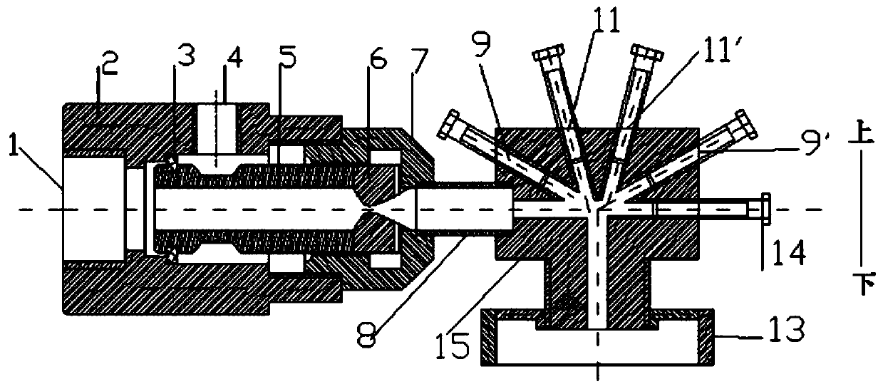

Image

  • Low-frequency ultrasonic electrostatic atomizing nozzle
  • Low-frequency ultrasonic electrostatic atomizing nozzle
  • Low-frequency ultrasonic electrostatic atomizing nozzle

Examples


Embodiment Construction

[0027] Embodiments of the present invention are described in detail below, examples of which are shown in the drawings, wherein the same or similar reference numerals designate the same or similar elements or elements having the same or similar functions throughout. The embodiments described below by referring to the figures are exemplary and are intended to explain the present invention and should not be construed as limiting the present invention.

[0028] In describing the present invention, it is to be understood that the terms "central", "longitudinal", "transverse", "length", "width", "thickness", "upper", "lower", "axial", The orientation or positional relationship indicated by "radial", "vertical", "horizontal", "inner", "outer", etc. is based on the orientation or positional relationship shown in the drawings, and is only for the convenience of describing the present invention and simplifying the description , rather than indicating or implying that the device or elem...


PUM


Abstract

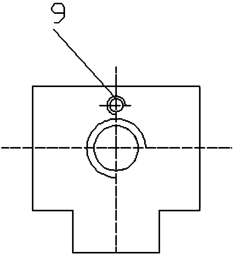
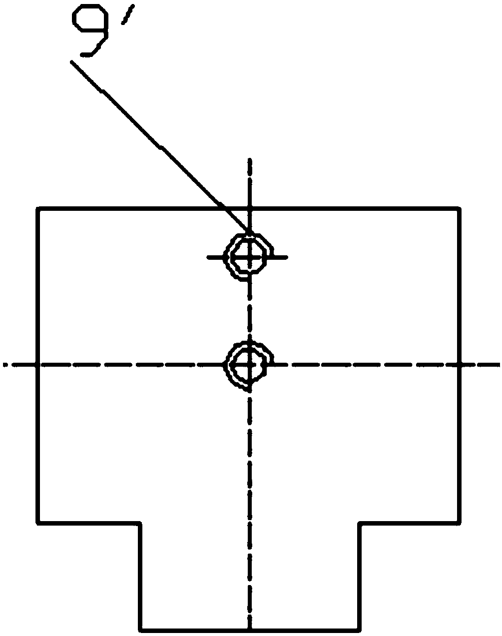
The invention provides a low-frequency ultrasonic electrostatic atomizing nozzle. The low-frequency ultrasonic electrostatic atomizing nozzle comprises an air inlet sleeve, a sealing ring, a liquid inlet hole, a flow guide pipe, a laval pipe, a fixed cap, a hollow stud, a resonance body, a plurality of bolts, an induction electrode and a high-voltage electrostatic generator; one end of the air inlet sleeve is connected with one end of the fixed cap; the flow guide pipe and the laval pipe are positioned in the space which is formed by the air inlet sleeve and the fixed cap; the hollow stud is connected with the fixed cap and the resonance body; a plurality of pairs of threaded holes are formed in the resonance body; each pair of threaded holes are symmetrical about the vertical center lineof the resonance body; the included angle between each pair of threaded holes and the horizontal plane is different; the bolts are arranged in the threaded holes correspondingly; and the induction electrode is arranged at a nozzle at the bottom of the resonance body, and is connected with the high-voltage electrostatic generator. High-pressure gas can crush water droplets at a supersonic speed togenerate mist droplets in different sizes, and electric charges can be induced from the mist droplets at the same time, so that the mist droplets are more effectively adsorbed to plants, and the utilization rate of a pesticide is improved.

Description

technical field [0001] The invention relates to the technical field of agricultural equipment, in particular to a low-frequency ultrasonic electrostatic atomizing nozzle. Background technique [0002] At present, the atomizing nozzles used in the field of atomizing cultivation are mainly piezoelectric ultrasonic atomizing nozzles and mechanical atomizing nozzles. The piezoelectric atomizing nozzles have a small spray volume and are only suitable for small-scale cultivation; while ordinary mechanical atomizing nozzles Although the amount of atomization is large, the droplet size produced by it is relatively large (greater than 100 μm) and the uniformity is poor, and it is difficult for large droplets to adsorb on the fine roots of plants. [0003] Therefore, the current spray technology mainly solves two problems: one is that the particle size of the droplets is too large and the size is difficult to adjust; the other is how to make the droplets fully and evenly adsorb on the...

Claims


Application Information

Patent Timeline
Patent Type & Authority Applications(China)
IPC IPC(8): B05B5/03B05B5/053
CPCB05B5/03B05B5/053
Inventor 高建民陈祥超何瑞陈杰栋
Owner 黑龙江省北为智能科技有限责任公司
Why Eureka
Try Eureka