
Knee joint prosthesis

A knee joint prosthesis and prosthesis technology, applied in the field of knee joint prosthesis, can solve the problems of fragility of ceramic femoral condyle prosthesis, reduced thickness of polymer inner lining, and high wear rate of tibial lining, so as to reduce fragmentation. risk, reducing metal ion precipitation, reducing the effect of friction coefficient

Pending Publication Date: 2019-04-23
ANHUI UNIVERSITY OF TECHNOLOGY AND SCIENCE
View PDF6 Cites 3 Cited by
  • Summary
  • Abstract
  • Description
  • Claims
  • Application Information

AI Technical Summary

Problems solved by technology

During the long-term friction and wear process of the friction pair formed by this pairing, toxic metal ions will be precipitated, which will accumulate to a certain concentration in the human body and cause chronic diseases. At the same time, the wear debris will induce osteolysis of the bone tissue around the prosthesis; The friction pair formed by this matching pair makes the wear rate of the polymer tibial liner very high. The most commonly used polymer material is ultra-high molecular weight polyethylene, and its annual wear is about 0.1-0.2mm. During the long-term friction process, Will cause the thickness of the polymer liner to decrease continuously, which will affect the strength of the tibial liner
In addition, there is another type of artificial knee prosthesis: ceramic femoral condyle prosthesis paired with polymer tibial liner, this pair has good wear resistance, very little wear, and no metal ion precipitation , has a good development prospect, but due to the inherent fragility of the ceramic itself, the ceramic femoral condyle prosthesis is easily broken, and it is still in the laboratory research stage and has no clinical application

Method used


Image

  • Knee joint prosthesis
  • Knee joint prosthesis
  • Knee joint prosthesis

Examples


Embodiment Construction

[0026] The specific implementation manner of the present invention will be described in further detail below by describing the embodiments with reference to the accompanying drawings.

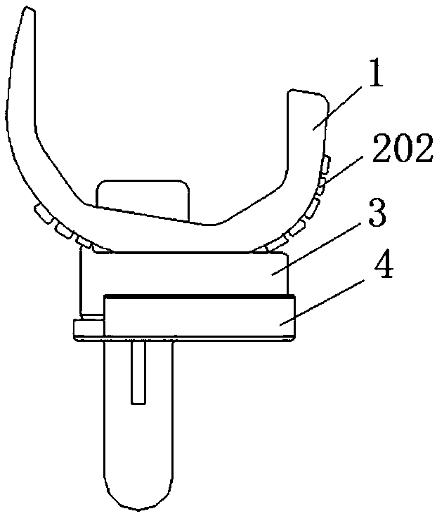
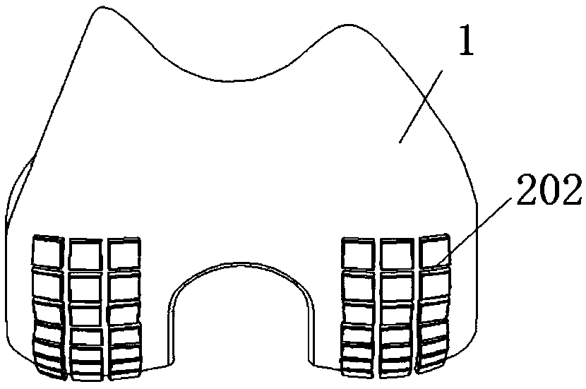
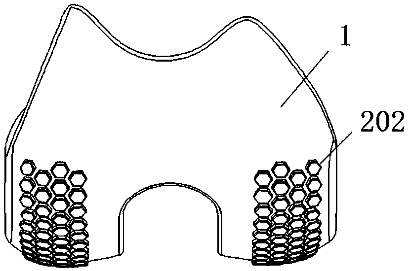
[0027] Knee joint prosthesis, including femoral condyle prosthesis, tibial liner, tibial plateau support, tibial liner is set on the tibial plateau support, the outer surface of the femoral condyle prosthesis corresponds to the upper surface of the tibial liner, and the outer surface of the femoral condyle prosthesis Or the upper surface of the tibial pad is provided with ceramic sheets for reducing the friction between the two. The ceramic sheets are a group, and a group of ceramic sheets are discretely distributed, which can be evenly or non-uniformly spaced. The non-uniform spacing arrangement can increase the contact area, thereby reducing the contact stress.

[0028] Among them, the inner surface of the femoral condyle prosthesis and the outer surface of the lower part of the tibial platea...


PUM


Abstract

The invention discloses a knee joint prosthesis. The knee joint prosthesis comprises a femoral condyle prosthesis, a pad and a tibial plateau bracket, wherein the pad is arranged on the tibial plateaubracket; a group of ceramic sheets for reducing the abrasion of the femoral condyle prosthesis and the pad are arranged on the femoral condyle prosthesis, distributed dispersedly, and connected withthe femoral condyle prosthesis through welding, and the convex curved surfaces of the ceramic sheets are in contact with the upper surface of the pad to form a friction pair. The ceramic sheets are distributed on the femoral condyle prosthesis in the knee joint prosthesis to separate the femoral condyle prosthesis from the tibial pad in order to reduce the abrasion loss of the femoral condyle prosthesis and the tibial pad; the friction between metal and a high-molecular polymer material is converted into the friction between the metal and the ceramics, the precipitation of metal ions, caused by the friction between the metal and the high-molecular polymer, is reduced, and the knee joint prosthesis has certain impact resistance and a noise reduction effects.

Description

technical field [0001] The invention relates to the technical field of biomedical engineering orthopedic internal implant prosthesis, in particular to a knee joint prosthesis. Background technique [0002] Artificial knee arthroplasty is an effective clinical treatment for knee joint injuries caused by trauma or disease. The artificial knee joint system consists of femoral condyle prosthesis, tibial liner, and tibial plateau support. As a biomaterial used in artificial knee prosthesis, it should not only achieve a good repair effect, relieve the pain of patients, restore the function of the knee joint, but more importantly, it should not have adverse effects on the tissues around the human knee joint. [0003] A common knee prosthesis consists of a metal femoral condyle, a polyethylene tibial liner, and a metal tibial plateau. The femoral condyle prosthesis and the tibial liner constitute a pair of friction pairs. The type of artificial knee joint currently used clinicall...

Claims


Application Information

Patent Timeline
IPC IPC(8): A61F2/38
CPCA61F2/3859A61F2/389A61F2002/3093A61F2002/30329A61F2310/00179
Inventor 韦山汪正宇王凡杨德玉宫国庆刘启元孙铜生时培成
Owner ANHUI UNIVERSITY OF TECHNOLOGY AND SCIENCE
Learn More