A Low RCS Ultra-Wideband Connected Long Slot Antenna Array Based on Resistive Metamaterial Loading
A metamaterial and ultra-broadband technology, which is applied to antenna unit combinations with different polarization directions, antennas, antenna grounding devices, etc., can solve the problem that the electromagnetic wave RCS reduction effect is not given, and achieve improved ability, improved performance, and reduced RCS Effect
- Summary
- Abstract
- Description
- Claims
- Application Information
AI Technical Summary
Problems solved by technology
Method used
Image
Examples
Embodiment 1
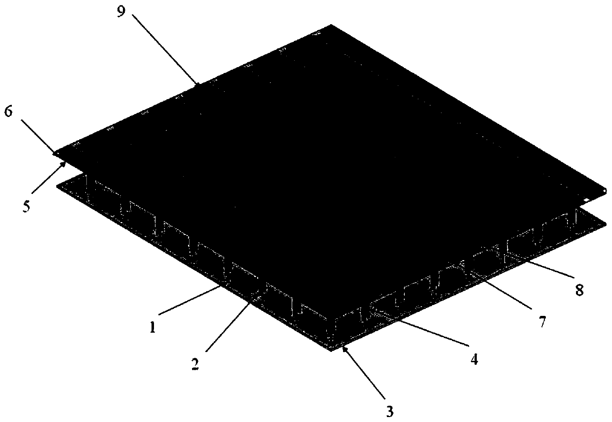
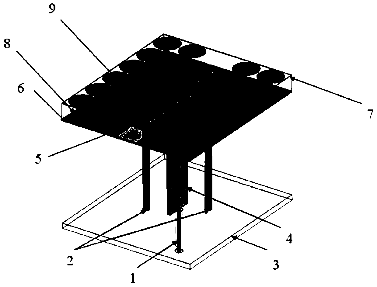
[0028] refer to Figure 1 to Figure 2 , Embodiment 1 is composed of a layer of periodic structure printed with closely arranged long groove units, using periodic boundary conditions to simulate the simulation of the present invention in an infinite array environment. The structure of the antenna unit of the present invention is described as follows: a coaxial feed structure 1; two grounded metal posts 2 for suppressing common-mode resonance; a metal floor 3 with a certain thickness; Gradient line balun 4; printed connected long slot antenna patch 5 with strong coupling effect; antenna dielectric substrate 6 for supporting the entire phased array antenna system structure; supporting dielectric substrate 7 for resistive electromagnetic metamaterial loading; Foam layer 8; circular resistive electromagnetic metamaterial 9 with ultra-broadband absorbing effect.
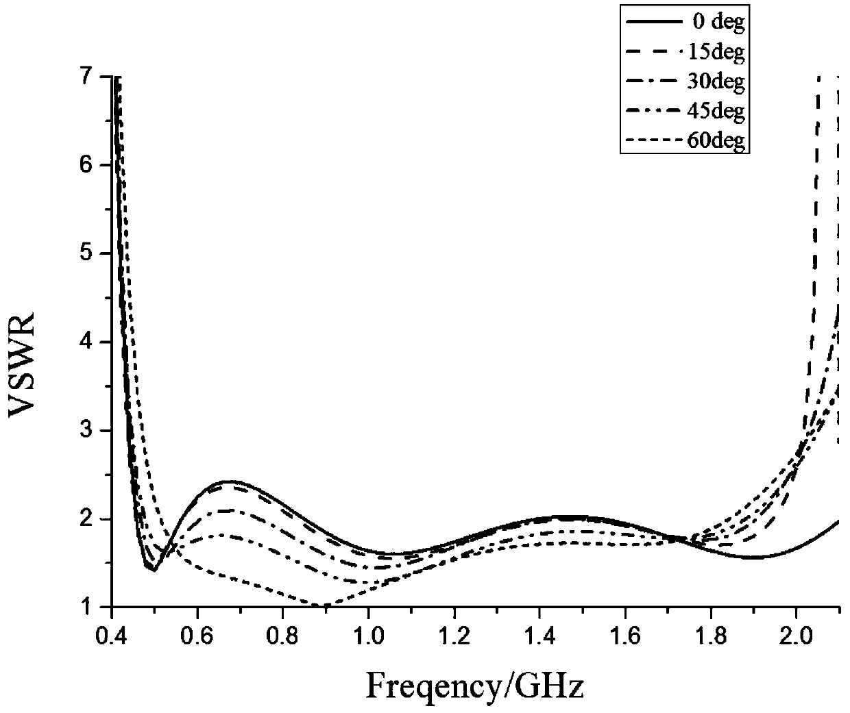
[0029] Figure 3 to Figure 6 The standing wave ratio and radiation characteristics of Example 1 during scanning are gi...
Embodiment 2
[0032] specifically. Each antenna element (such as figure 2 shown) are extended along the two-dimensional direction of the array respectively to form figure 1 An 8×8 resistive electromagnetic metamaterial-loaded low RCS ultra-broadband connected long-slot antenna array. Other structures are the same as those in Embodiment 1, and will not be repeated here.
[0033] Figures 11 to 12 show the radiation pattern of Example 2. It can be seen from Fig. 11 and Fig. 12 that the antenna array has stable beam pointing at different scanning angles of the E plane and the H plane, indicating that the radiation performance during scanning is good.
[0034] In this implementation example, the array is figure 2 An 8×8 array of periodic units is shown. based on figure 2 The described antenna unit can expand the infinite array environment to any practical finite array according to actual application requirements.
PUM
 Abstract
Description
Claims
Application Information
 - R&D
- Intellectual Property
- Life Sciences
- Materials
- Tech Scout
- Unparalleled Data Quality
- Higher Quality Content
- 60% Fewer Hallucinations
Browse by: Latest US Patents, China's latest patents, Technical Efficacy Thesaurus, Application Domain, Technology Topic, Popular Technical Reports.
© 2025 PatSnap. All rights reserved.Legal|Privacy policy|Modern Slavery Act Transparency Statement|Sitemap|About US| Contact US: help@patsnap.com


