
Low-cost millimeter wave beam scanning antenna applied to 5G mobile terminal

A mobile terminal and beam scanning technology, which is applied in the directions of antenna arrays, antennas, and antenna arrays that are powered independently, can solve problems such as poor performance indicators such as gain and complex antenna structures, and achieve high-precision feed phase, high beam gain, and The effect of large scanning angle

Active Publication Date: 2019-04-19
BEIJING INSTITUTE OF TECHNOLOGYGY
View PDF7 Cites 11 Cited by
  • Summary
  • Abstract
  • Description
  • Claims
  • Application Information

AI Technical Summary

Problems solved by technology

However, in the published literature, the feeding network of this method is not separated from the radiating antenna, the antenna structure is relatively complex, and the performance indicators such as gain are also poor

Method used


Image

  • Low-cost millimeter wave beam scanning antenna applied to 5G mobile terminal
  • Low-cost millimeter wave beam scanning antenna applied to 5G mobile terminal
  • Low-cost millimeter wave beam scanning antenna applied to 5G mobile terminal

Examples


Embodiment Construction

[0028] The implementation of the present invention will be described in detail below in conjunction with the drawings and examples.

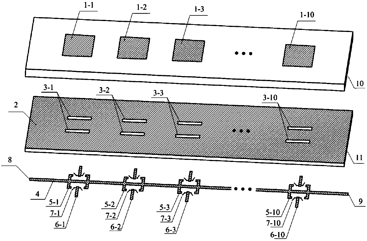
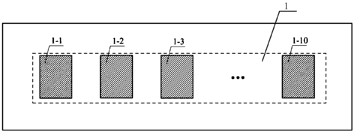
[0029] As a preferred embodiment of the present invention, the three-dimensional structural exploded view and side view of the beam scanning antenna described in the present invention are as follows figure 1 with figure 2 shown. The antenna includes a patch array 1, a floor 2, a coupling slot 3, a feeding microstrip line 4, a branch microstrip line 5, a suspension microstrip line 6, a switch 7, a signal input port 8, a signal output port 9, and a dielectric block 10 and media block 11. The two media blocks have the same area and are tightly fitted together. Three layers of metal are printed on the upper surface of the dielectric block 10 , the upper surface of the dielectric block 11 and the lower surface of the dielectric block 11 respectively. The specific structures of the three metal layers are as follows: image 3 , Figure 4 with ...


PUM


Abstract

The invention relates to a low-cost millimeter wave beam scanning antenna applied to a 5G mobile terminal, which is suitable for the field of mobile communication. The low-cost millimeter wave beam scanning antenna comprises a patch array, a floor provided with a coupling groove and a feed microstrip line provided with a 2-bit phase shifter; the patch array is formed by ten equally spaced rectangular patch units; the lower portion of each patch unit is provided with a pair of coupling grooves, the lower portion of each pair of coupling grooves is provided with one 2-bit phase shifter, each phase shifter leads out four branch microstrip lines from the center feed microstrip line, and the length of each branch line is controlled by a binary switch to provide a phase change of 0 degree, 90 degrees, 180 degrees and 270 degrees. The traveling wave feature of the leaky wave antenna is employed to construct the phase shifter to reduce the antenna cost, and the radiation antenna and the feed network are respectively put at two sides of the floor to increase the degree-of-freedom of design.

Description

technical field [0001] The invention belongs to the field of antenna design of wireless communication technology, in particular to a low-cost beam scanning antenna applied to 5G mobile terminals. Background technique [0002] The millimeter wave frequency band will play an important role in the upcoming 5G mobile communication system. The International Telecommunication Union (ITU), the United States, Japan and other countries have adopted the 28GHz frequency band as the main millimeter wave frequency band for 5G mobile communications. In this frequency band, the physical size of the antenna is small and the frequency bandwidth is wide, which is suitable for high-speed wireless data transmission. In order to overcome the disadvantage of large millimeter-wave path loss and provide wider spatial coverage, millimeter-wave antennas in 5G mobile communications need to have high gain and beam dynamic scanning capabilities. Phased array technology is a widely used implementation ...

Claims


Application Information

Patent Timeline
Patent Type & Authority Applications(China)
IPC IPC(8): H01Q21/06H01Q21/00H01Q1/50H01Q1/36H01Q1/38
CPCH01Q1/36H01Q1/38H01Q1/50H01Q21/0075H01Q21/0081H01Q21/065
Inventor 邓长江吕昕
Owner BEIJING INSTITUTE OF TECHNOLOGYGY
Learn More