A drying device for pipe parts

A drying device and a technology for pipe parts, which are applied in the field of mechanical parts processing, can solve the problems of affecting the service life of mechanical parts, water droplets are not easy to clean, and parts are damaged, so as to improve the rebound effect and improve the drying effect. Efficiency, the effect of increasing the contact area

Active Publication Date: 2020-10-16
福建泉州市剑井贸易有限公司
View PDF5 Cites 0 Cited by
  • Summary
  • Abstract
  • Description
  • Claims
  • Application Information

AI Technical Summary

Problems solved by technology

[0003] At present, in the production process of pipe parts, many processes need to go through, and there will be oil, debris and other impurities on the surface and in the holes. If the pipe parts after cleaning are not dried effectively, it will affect the machine. The service life of parts. Some ovens in the prior art evaporate and dry the water droplets adhered to the pipe parts by controlling the temperature rise in the box. Since the water droplets adhere to different positions on the pipe parts, some gaps between The water drops are not easy to clean, and if the drying temperature in the oven is increased, the parts may be damaged. Therefore, a drying device for pipe parts is proposed to solve the above problems

Method used


Image

  • A drying device for pipe parts
  • A drying device for pipe parts
  • A drying device for pipe parts

Examples


Embodiment 1

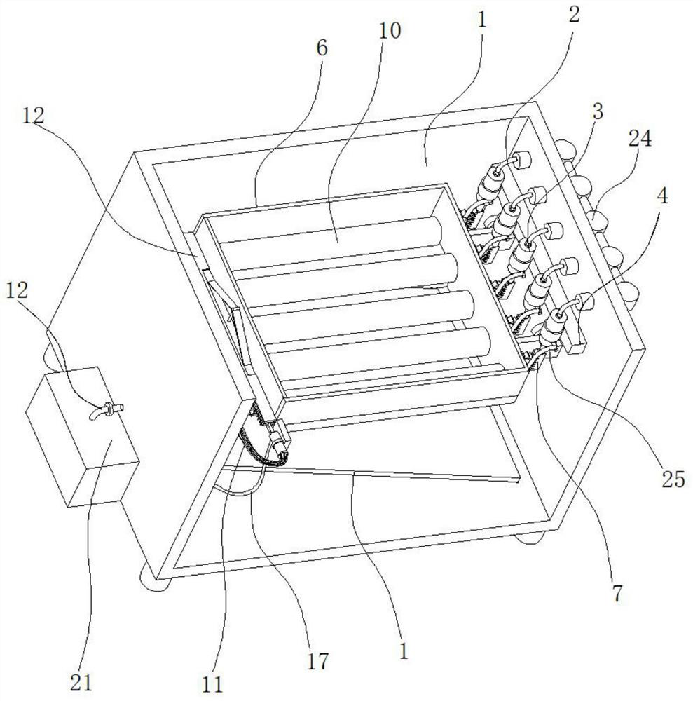
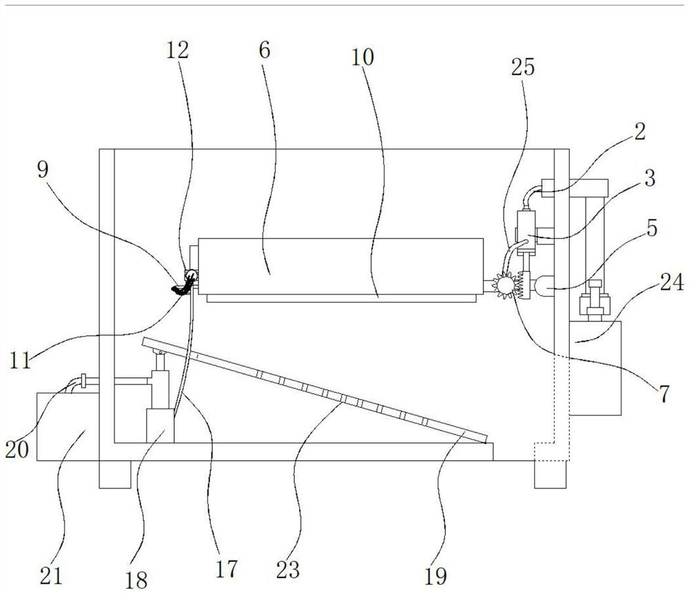
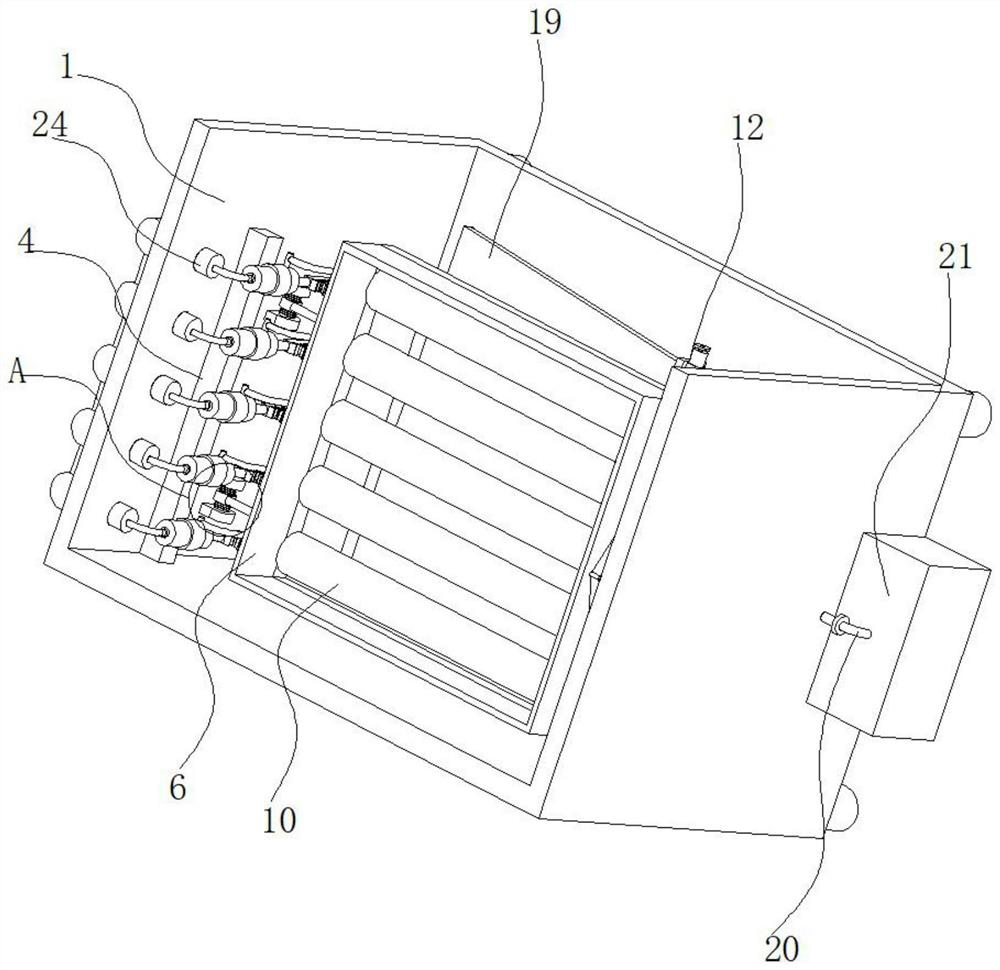
[0037] refer to figure 1 , figure 2 , image 3 and Figure 5, a drying device for pipe parts, including a box body 1 and an electric heating steam generating mechanism 24, and the electric heating steam generating mechanism 24 is connected to the outer side wall of the box body 1, and the air outlet of the electric heating steam generating mechanism 24 passes through the first A connecting hose 2 is connected with a first drive assembly 3, the longitudinal inner wall of the box body 1 is connected with a fixed piece 4 and a movable connection piece 5 in the vertical direction, the first drive assembly 3 is connected on the fixed piece 4, and the movable connection piece 5. One end away from the inner side wall of the box body 1 is connected with a fixed frame 6, the driving end of the first drive assembly 3 is connected with a transmission assembly 7 acting on the fixed frame 6, and the outer side wall of the fixed frame 6 close to the movable connecting piece 5 is connecte...

Embodiment 2

[0039] refer to figure 1 , figure 2 , image 3 , Figure 5 , Figure 7 and Figure 8 , a drying device for pipe parts, basically the same as Embodiment 1, further, the first drive assembly 3 includes a sleeve 31, the top of the sleeve 31 is connected with an air intake pipe 32, and the air intake pipe 32 passes through the first A connecting hose 2 is communicated with the air outlet of the electric heating steam generating mechanism 24, an air outlet pipe 33 is connected to the outer side wall of the sleeve 31 near the bottom end, and the air outlet pipe 33 is connected with the first communication pipe 8 through the fourth connecting hose 25, A piston 34 is slidably connected in the cylinder 31, and a regulating rod 35 is connected to the side of the piston 34 away from the air inlet pipe 32. The outer wall of the regulating rod 35 located in the sleeve 31 is sleeved with a return spring 36, and the two ends of the return spring 36 are respectively connected to each oth...

Embodiment 3

[0043] refer to Figure 1-5 , a drying device for pipe parts, which is basically the same as Embodiment 1, and further, the movable connecting piece 5 includes a U-shaped fixing rod 51, and the horizontal section of the U-shaped fixing rod 51 is covered with a sleeve rod 52, and the sleeve rod A connecting rod 53 is connected between 52 and the fixed frame 6, and the two ends of the sleeve rod 52 are connected with a force spring 54, and the force spring 54 is sleeved on the rod wall of the horizontal section of the U-shaped fixed rod 51; Fixed the rebound effect of frame 6.


PUM


Abstract

The invention discloses a drying device for pipe parts, and belongs to the technical field of processing of mechanical parts. The drying device for the pipe parts comprises a box body and an electricheating steam generation mechanism, wherein the electric heating steam generation mechanism is connected to the outer side wall of the box body, an air outlet of the electric heating steam generationmechanism is connected with a first driving assembly through a first connecting hose, a fixed part and a movable connecting part are connected to the longitudinal inner side wall of the box body in the vertical direction, and the end, away from the inner side wall of the box body, of the movable connecting part is connected with a fixed frame. According to the drying device for the pipe parts, vapor is used for heat transmission and drying, so that the problem of damage to the machine pipe parts caused by high temperature is effectively solved; the fixed frame is driven to vibrate through steam while drying is carried out so that water drops adhered to the surfaces of the pipe parts can be rapidly reduced, and the drying efficiency is improved; and meanwhile, a drying cylinder is driven torotate while the fixed frame is driven to vibrate through the steam, so that the contact area between the drying cylinder and the pipe parts is increased, and the drying uniformity is improved.

Description

technical field [0001] The invention relates to the technical field of mechanical parts processing, in particular to a drying device for pipe parts. Background technique [0002] Tube parts are important parts that make up machinery and machines. Tube parts need to be cleaned during the production process to remove stains on the surface of the parts. [0003] At present, in the production process of pipe parts, there are many processes that need to go through, and there will be impurities such as oil stains and debris on the surface and in the holes. If the cleaned pipe parts are not effectively dried, it will affect the mechanical The service life of the parts, some ovens in the prior art evaporate and dry the water droplets adhering to the pipe parts by controlling the temperature rise in the box. The water droplets are not easy to clean. If the drying temperature in the oven is increased, the parts may be damaged. Therefore, a drying device for pipe parts is proposed to ...

Claims


Application Information

Patent Timeline
Patent Type & Authority Patents(China)
IPC IPC(8): F26B11/02F26B21/00F26B25/02F26B25/04F26B25/16F26B25/00
CPCF26B11/02F26B21/004F26B21/005F26B25/00F26B25/02F26B25/04F26B25/16
Inventor 初晓成唐晓芬庄宪初
Owner 福建泉州市剑井贸易有限公司
Why Eureka
Try Eureka