Rod heat treatment equipment

A technology of heat treatment equipment and rods, applied in heat treatment equipment, heat treatment furnace, heat treatment process control and other directions, can solve the problems of uneven heating, high procurement cost, inconvenient placement, etc., and achieve the effect of uniform heating

Active Publication Date: 2019-04-19
六安市志鹏金属加工有限公司
View PDF3 Cites 2 Cited by
  • Summary
  • Abstract
  • Description
  • Claims
  • Application Information

AI Technical Summary

Problems solved by technology

[0002] In actual production, there is a kind of bar that needs to be strengthened. In the process of strengthening the performance of these bars, the bar needs to be heated. The existing heating device is usually directly heated by an electric furnace. In the high-temperature furnace body, they are neatly stacked into stacks. It is inconvenient to place the rods and it is difficult to realize the uniform arrangement of the rods in the heating furnace, so that there is a large difference in the heat of different rods during the heat treatment of the rods, and the heat treatment effect is not good. And this This kind of rod needs to be kept warm for a long time when heating. The existing charcoal furnace heating is difficult to meet the requirements. However, some heat treatment equipment on the market is very high in automation and has a very good heating effect. Although it is excellent in temperature control, it is installed It is inconvenient to clamp and cannot be well adapted to the heating of rods, and one of the biggest problems is that the purchase cost is extremely high, which is neither economical nor suitable for rods of non-precision parts. At present, special heat treatment equipment made by various factories There is also the above-mentioned uneven heating and inconvenient placement. However, the heating efficiency of the rods is low by using electric heating or the air in the charcoal heating furnace to heat the rods. The most important thing is that the heating speed is slow. Through the air Heating to realize the heating of rods cannot meet the process requirements in terms of heating speed, and the entire heating system is unstable

Method used


Image

  • Rod heat treatment equipment
  • Rod heat treatment equipment
  • Rod heat treatment equipment

Examples


Embodiment Construction

[0025] The implementation of the present invention will be illustrated by specific specific examples below, and those skilled in the art can easily understand other advantages and effects of the present invention from the contents disclosed in this specification.

[0026] Below in conjunction with accompanying drawing and embodiment the present invention will be further described:

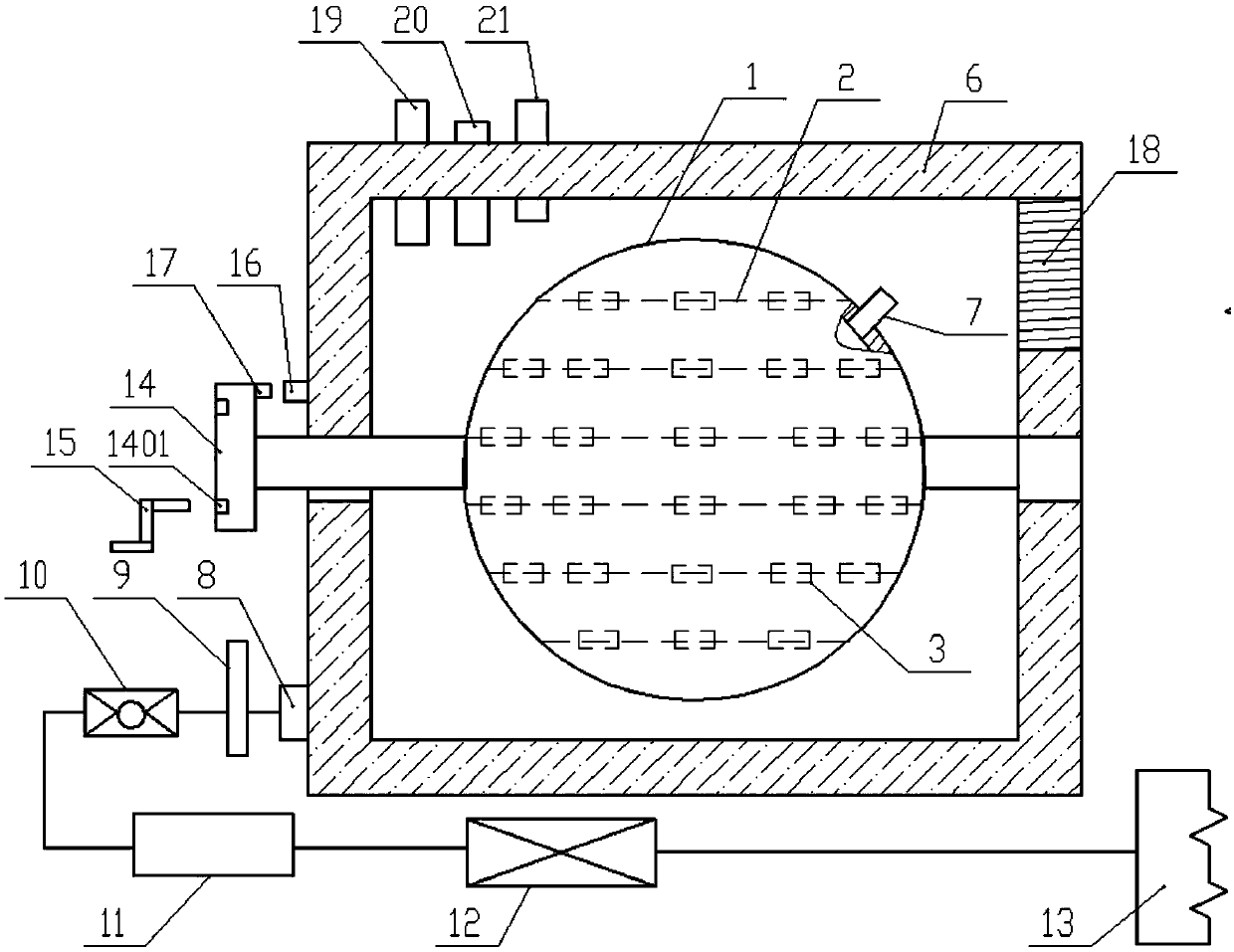
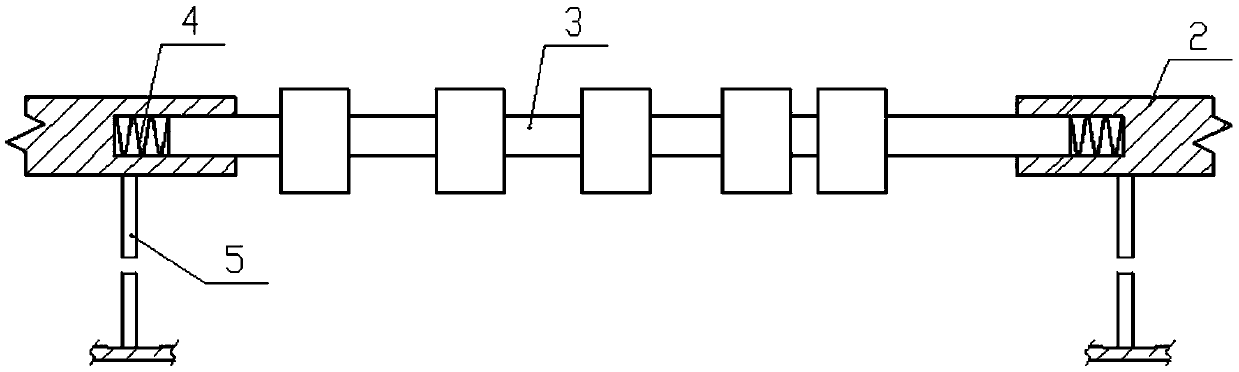
[0027] Such as figure 1 As shown in -4, a rod heat treatment equipment includes a heating furnace 1 for placing a rod 3, the heating furnace 1 is spherical, the inside of the heating furnace 1 is hollow and has a uniform wall thickness, and the heating furnace 1 is filled with There is heating oil, and multiple layers of clamping rods 2 are arranged parallel to each other in the heating furnace 1 for 2 clamping rods. The clamping rods 2 are rod-shaped and arranged in a straight line at intervals. The rods 2 are all fixed in the heating furnace 1 through the connecting rod 5, the gap between two ad...


PUM

PropertyMeasurementUnit
thermal resistanceaaaaaaaaaa

Abstract

The invention discloses rod heat treatment equipment which comprises a heating furnace for containing rods. The heating furnace is spherical, the heating furnace is internally hollow and is uniform inwall thickness, the heating furnace is filled with heating oil , the heating furnace is internally provided with a plurality of layers of clamping rods for clamping the rods in parallel, the rod heattreatment equipment further comprises an external stove for containing the heating furnace, a constant pressure control valve comprises a valve body, a control hole is formed in the axis of the valvebody and formed by coaxially connecting two sections of conical through holes in a mirror symmetry butting mode, and small ports of the two through holes are integrally connected. A sensing element used for detecting flowing of fluid in a pipeline is arranged on the pipeline between a liquid drainage pipe and the constant pressure control valve, and the sensing element is connected with the controller. The rod heat treatment equipment is easy and convenient to operate, capable of carrying out even heating while containing multiple rods, stable and reliable in heat supply system and extremelygood in heat treatment effect.

Description

technical field [0001] The invention belongs to the technical field of metal heat treatment, in particular to a tool for heat treatment of rods. Background technique [0002] In actual production, there is a kind of bar that needs to be strengthened. In the process of strengthening the performance of these bars, the bar needs to be heated. The existing heating device is usually directly heated by an electric furnace. In the high-temperature furnace body, they are neatly stacked into stacks. It is inconvenient to place the rods and it is difficult to achieve a uniform arrangement of the rods in the heating furnace. As a result, there is a large difference in the heating of different rods during the heat treatment of the rods, and the heat treatment effect is not good. And this This kind of rod needs to be kept warm for a long time when heating. The existing charcoal furnace heating is difficult to meet the requirements. However, some heat treatment equipment on the market has...

Claims


Application Information

Patent Timeline
Patent Type & Authority Applications(China)
IPC IPC(8): C21D9/00C21D11/00
CPCC21D9/0025C21D9/0031C21D9/0075C21D11/00
Inventor 不公告发明人
Owner 六安市志鹏金属加工有限公司
Why Eureka
Try Eureka