
Diagnostic system and method for non-uniform plasma electron density

A plasma and electron density technology, applied in the direction of plasma, electrical components, etc., can solve the problems of limited plasma parameters, few application conditions, limited parameters, etc., and achieve the effect of low test cost and high test efficiency

Active Publication Date: 2019-04-16
SHANGHAI RADIO EQUIP RES INST
View PDF7 Cites 23 Cited by
  • Summary
  • Abstract
  • Description
  • Claims
  • Application Information

AI Technical Summary

Problems solved by technology

However, the plasma parameters obtained by spectroscopy are limited, and it is necessary to determine the composition of the discharge gas and calibrate it with a known standard light source. The process is complicated and can only measure the plasma environment in a transparent cavity made of glass and other materials, and the plasma discharge temperature is not suitable. Too high, few conditions apply
[0005] In the past, the research on the diagnosis of plasma electron density mainly focused on the probe method and optical method. Although there is a certain basis for the diagnosis of plasma electron density, the probe method is not suitable for diagnosis in a high-pressure environment. The "sheath expansion effect" has a significant impact on the results. Using the probe method to diagnose the plasma electron density requires consideration of the test environment and selection of a suitable theory to calibrate the probe data, which has certain limitations.
However, the plasma parameters obtained by spectroscopy are limited, and it is necessary to determine the composition of the discharge gas and calibrate it with a known standard light source. The process is complex and can only measure the plasma environment in a transparent cavity made of glass and other materials. High, few conditions apply

Method used


Image

  • Diagnostic system and method for non-uniform plasma electron density
  • Diagnostic system and method for non-uniform plasma electron density
  • Diagnostic system and method for non-uniform plasma electron density

Examples


Embodiment Construction

[0044] The present invention will be further elaborated below by describing a preferred specific embodiment in detail in conjunction with the accompanying drawings.

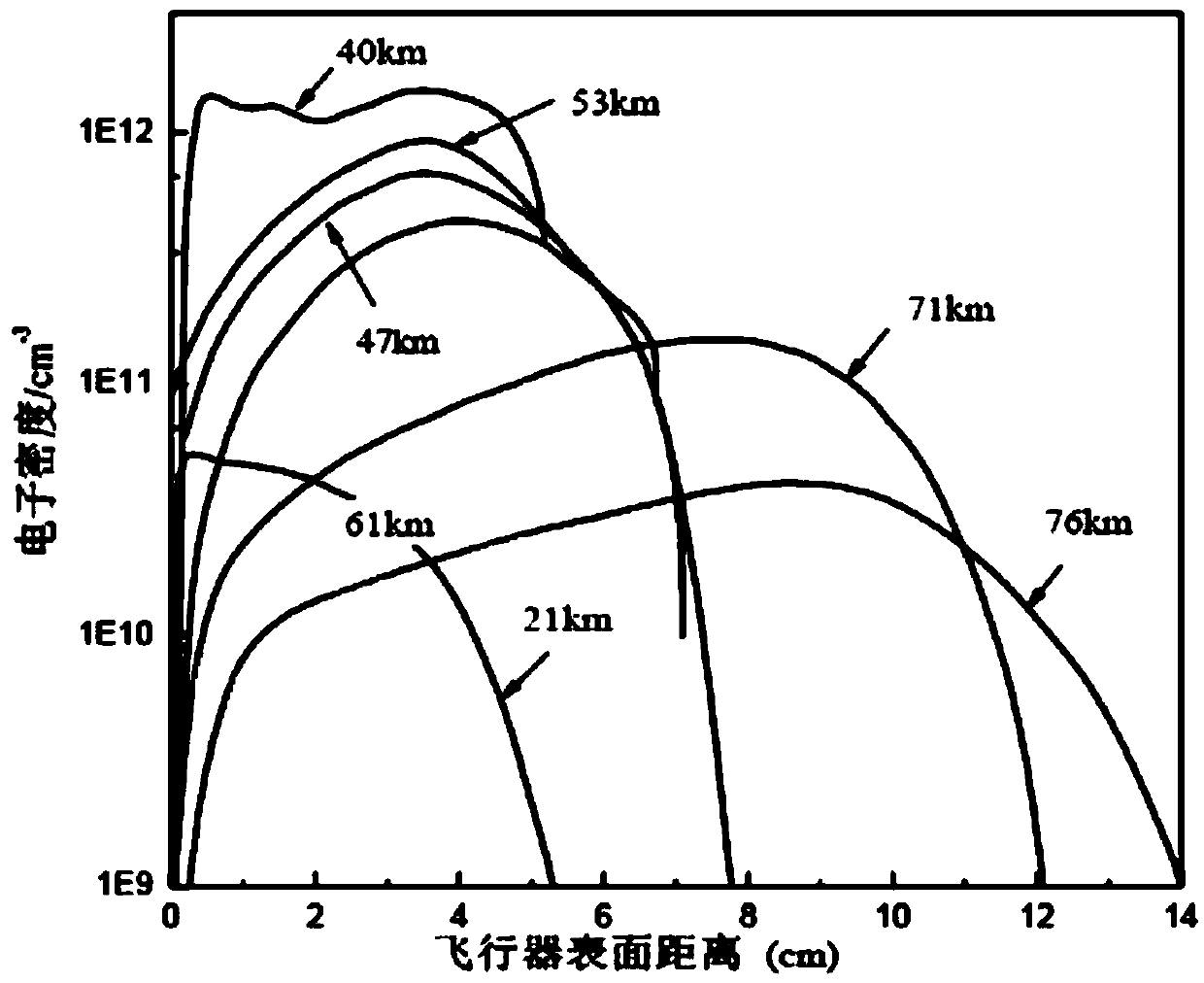
[0045] The plasma sheath of hypersonic vehicle has the basic characteristics of wide parameter range, high collision frequency and non-uniformity. The high-speed target plasma has obvious non-uniform distribution characteristics in the radial direction, and the change gradient is large, such as figure 1 In the section shown, within a thickness range of 10 cm, the electron density variation span is as high as more than 3 orders of magnitude; and there is also serious non-uniformity in the axial electron density of the high-speed target plasma. In order to simulate characteristics such as wide parameter range and non-uniformity of plasma electron number density, such as overcoming the shortcomings of the existing electron density testing technology for non-uniform plasma produced by hypersonic aircraft, a non-unifo...


PUM

PropertyMeasurementUnit
Diameteraaaaaaaaaa

Abstract

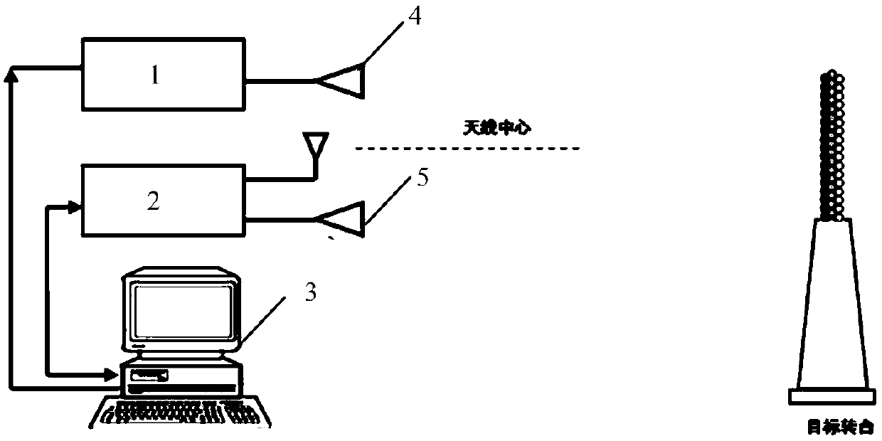
The invention provides a diagnostic system for non-uniform plasma electron density, including the following parts: a plasma generator, disposed in front of the calibrator; an ultra-wideband antenna, including a receiving antenna and a transmitting antenna disposed on the same side of the plasma generator; a time domain narrow-pulse source, connected to the transmitting antenna; a high-speed sampling digital oscilloscope, connected to the transmitting antenna and the receiving antenna, and used for recording and processing a transmitting signal of the transmitting antenna and a receiving signalof the receiving antenna; and a programmable power supply system, respectively connected to the time domain narrow-pulse source, the high-speed sampling digital oscilloscope and the plasma generator,and used to trigger the time domain narrow-pulse source, control the discharge power of the plasma generator, and record different discharge power states of the plasma to obtain basic plasma parameters under different discharge states. The system provided by the invention has the advantage of simulating a more accurate environment of super-sonic target surface plasma sheath, and having high testefficiency and low test cost.

Description

technical field [0001] The invention relates to the technical field of microwave testing, in particular to a diagnostic system and method for non-uniform plasma electron density. Background technique [0002] Plasma refers to the aggregated state of matter containing a large number of positively and negatively charged particles with approximately equal numbers of charges. Plasma is generated mainly through energy transport, which causes charge transport. When particles with sufficient energy collide with gas molecules, electrons and ions are generated, thereby forming a plasma. During the high-speed flight of a hypersonic vehicle, the extremely high temperature on the surface will ionize the gas molecules, thereby forming a plasma, which covers the surface of the vehicle to form a plasma sheath. The plasma sheath has an extremely high electron density, which will attenuate the power of electromagnetic wave propagation, resulting in distortion of communication and detection ...

Claims


Application Information

Patent Timeline
IPC IPC(8): H05H1/00
CPCH05H1/0062
Inventor 贾洁姝梁子长许勇刚郭良帅韩如冰
Owner SHANGHAI RADIO EQUIP RES INST
Learn More