
Composite micro-energy system suitable for small load and energy management method thereof

An energy management and micro-energy technology, which is applied in electric vehicles, electrical components, transportation and packaging, etc., can solve the problems of rare energy management methods for high-efficiency composite micro-energy systems, difficulty in applying power consumption, and complicated rules, so as to avoid system energy. Insufficient, the energy management method is simple and effective, and the charging power is gentle

Inactive Publication Date: 2019-04-12
TSINGHUA UNIV
View PDF8 Cites 9 Cited by
  • Summary
  • Abstract
  • Description
  • Claims
  • Application Information

AI Technical Summary

Problems solved by technology

Patent CN 102951144B and patent CN 105151040B respectively disclose the self-adjusting neural network energy management method based on the minimum power loss algorithm and the hybrid electric vehicle energy management method based on power spectrum self-learning prediction. These two energy management methods are relatively complicated and difficult to apply For wireless sensor nodes, which consume low power and are small in size
Patent CN 104163116B discloses an energy management method for a composite energy storage system for vehicles, which is simpler than the previous two methods, but the method is only applicable to electric vehicles, and the rules are still slightly complicated
[0007] At present, energy management methods for high-efficiency composite micro-energy systems that can be applied to small load fields such as wireless sensor nodes are still relatively rare.

Method used


Image

  • Composite micro-energy system suitable for small load and energy management method thereof
  • Composite micro-energy system suitable for small load and energy management method thereof
  • Composite micro-energy system suitable for small load and energy management method thereof

Examples


Embodiment

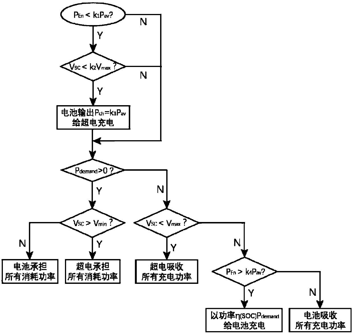
[0044] image 3 Shown is the algorithm flow chart of the energy management method of the composite micro-energy system; the main steps are as follows:

[0045] Step 1: Determine whether the environmental energy is relatively weak, if yes, go to step 2, otherwise skip to step 4. The judgment method is to compare the collected environmental energy with the reference value, that is, judge P En 1 P av Whether it is established. Where P av Is the average power consumption of the load, k 1 To approach the coefficient of 1, it should be set according to the specific composite micro energy system configuration.

[0046] Step 2: Determine whether the remaining energy storage of the super capacitor is low, if yes, go to step 3, otherwise skip to step 4. The judgment condition is V SC 2 V max , The coefficient k 2 It is related to the load power consumption and the capacity of the super capacitor, satisfying 1 / 32 <1.

[0047] Step 3: Lithium battery is charged for super capacitor, charg...


PUM


Abstract

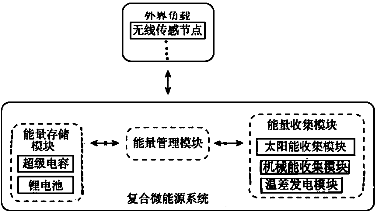
The invention discloses a composite micro-energy system suitable for a small load and an energy management method thereof, and belongs to the technical field of composite micro-energy management. Thecomposite micro-energy system consists of an environmental energy collection module, an energy management module and an energy storage module connected in series, and the energy management module is connected with a small load. The energy management method of the composite micro-energy system is that the energy management module collects the power consumption information of the small load, the power generation state of the energy collection module and the power storage state information of the energy storage module. As such, the information energy management module decides to charge or discharge the energy storage module, rationally distributes the charge and discharge power of the supercapacitor and the lithium battery in the energy storage module, and gives full play to the respective advantages of the energy storage of the lithium battery and the energy storage of the supercapacitor, thereby improving the reliability of the system, ensuring that sufficient energy is supplied to thesmall load, and ensuring the stable operation. The method is simple and effective, and prolongs the life of the system.

Description

Technical field [0001] The invention belongs to the technical field of composite micro-energy management, and particularly relates to a composite micro-energy system suitable for small loads and an energy management method thereof. Background technique [0002] With the rapid development of Microelectromechanical Systems (MEMS) and micro energy technology, wireless sensor network (Wireless Sensor Network, WSN) technology has gradually matured and is widely used in military, aviation, transportation, explosion protection, disaster relief, and environmental protection. Monitoring, medical and health and other fields. The wireless sensor network is composed of a large number of wireless sensor nodes, and each wireless sensor node has the functions of information collection, signal processing and data transmission. [0003] Due to the huge number of nodes and wide distribution areas, and many wireless sensor nodes are located in remote and hard-to-reach areas such as the wild, their m...

Claims


Application Information

Patent Timeline
Patent Type & Authority Applications(China)
IPC IPC(8): H02J7/34
CPCH02J7/34H02J7/345
Inventor 尤政戚南剑王晓峰
Owner TSINGHUA UNIV
Learn More