
An intelligent power supply method for a multi-battery system

An intelligent power supply and multi-battery technology, applied in the field of smart grid, can solve the problems of not taking into account the cost of energy storage devices and the number of times of use, etc., and achieve the effect of intelligent deployment, optimization of times of use, and cost reduction

Active Publication Date: 2022-05-20
C-SMARTLINK INFORMATION TECH CO LTD
View PDF0 Cites 0 Cited by
  • Summary
  • Abstract
  • Description
  • Claims
  • Application Information

AI Technical Summary

Problems solved by technology

[0002] In the existing technology, the intelligent deployment of the power grid has gradually gained the attention of practitioners with the optimization of the control chip. With the gradual popularization of new energy power generation, the use of new energy sources such as photovoltaics and wind power for power generation is being widely used. At the same time, batteries are used as Backup energy storage, on the one hand, it can effectively carry out backup energy storage. However, when it is used as backup energy storage, due to the stability of photovoltaic, wind power and other power generation units, it will be used more frequently, and the service life of the battery will affect the cost of the entire grid. Plays a key role. How to optimize and control the number of times the battery is used is something that needs to be paid attention to in the current distributed power generation and the future smart grid. Then, in the existing technology, the battery is only used as backup energy, such as UPS. For emergency start-up or energy supplementation, the cost of energy storage devices such as batteries is not considered according to the internal specific state of distributed power generation or the transmission efficiency of electric power, etc.

Method used


Image

  • An intelligent power supply method for a multi-battery system
  • An intelligent power supply method for a multi-battery system
  • An intelligent power supply method for a multi-battery system

Examples


Embodiment Construction

[0036] In order to make the objectives, technical solutions and advantages of the present invention clearer, the present invention will be described in further detail below in conjunction with the accompanying drawings and their embodiments; it should be understood that the specific embodiments described here are only used to explain the present invention and are not intended to to limit the present invention. Other systems, methods and / or features of this embodiment will become apparent to those skilled in the art after reviewing the following detailed description. It is intended that all such additional systems, methods, features and advantages be included within this description, be within the scope of the invention, and be protected by the following claims. Additional features of the disclosed embodiments are described in, and will be apparent from, the following detailed description.

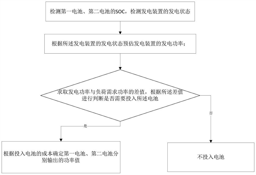
[0037] figure 1 It is a schematic diagram of the intelligent power supply method of t...


PUM


Abstract

The invention discloses an intelligent power supply method for a multi-battery system, comprising at least two batteries, a first battery and a second battery, including the following steps: (1) Detecting the SOC of the first battery and the second battery, and detecting the SOC of the power generation device Power generation state; (2) Estimating the power generation power of the power generation device according to the power generation state of the power generation device; (3) Finding the difference between the power generation power and the power demanded by the load, and judging whether it is necessary to put in the battery according to the difference ; (4) Determine the output power values ​​of the first battery and the second battery respectively according to the cost of the input battery. The invention can adjust the optimal output of the multi-battery system according to the proportion of the power supply of the distributed power supply, reduce the single output power of the battery, and realize the optimization of the use times of the multi-battery.

Description

technical field [0001] The invention relates to the technical field of smart grids, in particular to an intelligent power supply method for a multi-battery system. Background technique [0002] In the existing technology, the intelligent deployment of the power grid has gradually gained the attention of practitioners with the optimization of the control chip. With the gradual popularization of new energy power generation, the use of new energy sources such as photovoltaics and wind power for power generation is being widely used. At the same time, batteries are used as Backup energy storage, on the one hand, it can effectively carry out backup energy storage. However, when it is used as backup energy storage, due to the stability of photovoltaic, wind power and other power generation units, it will be used more frequently, and the service life of the battery will affect the cost of the entire grid. Plays a key role. How to optimize and control the number of times the battery...

Claims


Application Information

Patent Timeline
Patent Type & Authority Patents(China)
IPC IPC(8): H02J7/00H01M10/44H02J3/32
CPCH02J7/0021H01M10/441H02J3/32H02J2203/20Y02E60/10
Inventor 不公告发明人
Owner C-SMARTLINK INFORMATION TECH CO LTD
Learn More