
Millimeter wave passive multi-beam array device for mobile terminal and implementation method of millimeter wave passive multi-beam array device

A technology of mobile terminal and millimeter wave, which is applied in directions such as independently powered antenna arrays, mid-position feeds between antenna endpoints, and antenna arrays. and other problems, to achieve the effect of facilitating mass production, simple structure, and easy processing

Pending Publication Date: 2019-04-12
SOUTHEAST UNIV
View PDF12 Cites 6 Cited by
  • Summary
  • Abstract
  • Description
  • Claims
  • Application Information

AI Technical Summary

Problems solved by technology

However, the use of a single antenna or a single antenna array cannot meet the needs of mobile terminal equipment to cover all directions in the entire three-dimensional space.
For this practical problem, the industry has no clear solution so far, and it is urgent to propose a new method

Method used


Image

  • Millimeter wave passive multi-beam array device for mobile terminal and implementation method of millimeter wave passive multi-beam array device
  • Millimeter wave passive multi-beam array device for mobile terminal and implementation method of millimeter wave passive multi-beam array device
  • Millimeter wave passive multi-beam array device for mobile terminal and implementation method of millimeter wave passive multi-beam array device

Examples


Embodiment Construction

[0025] In order to describe the technical solution disclosed in the present invention in detail, further elaboration will be made below in conjunction with the accompanying drawings and specific embodiments.

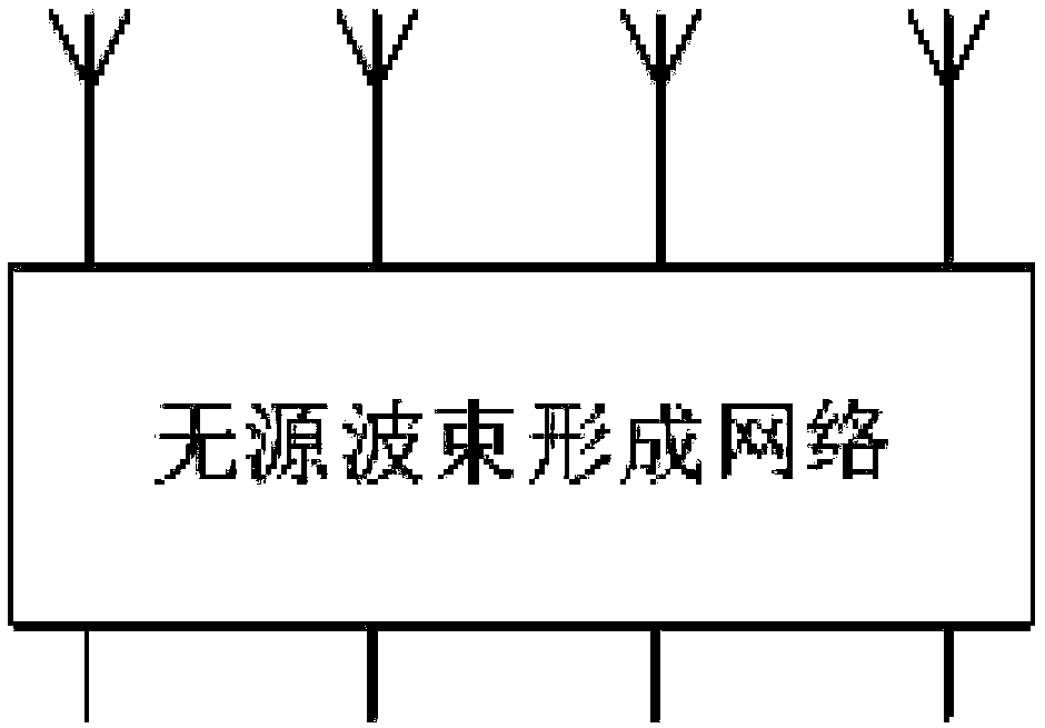
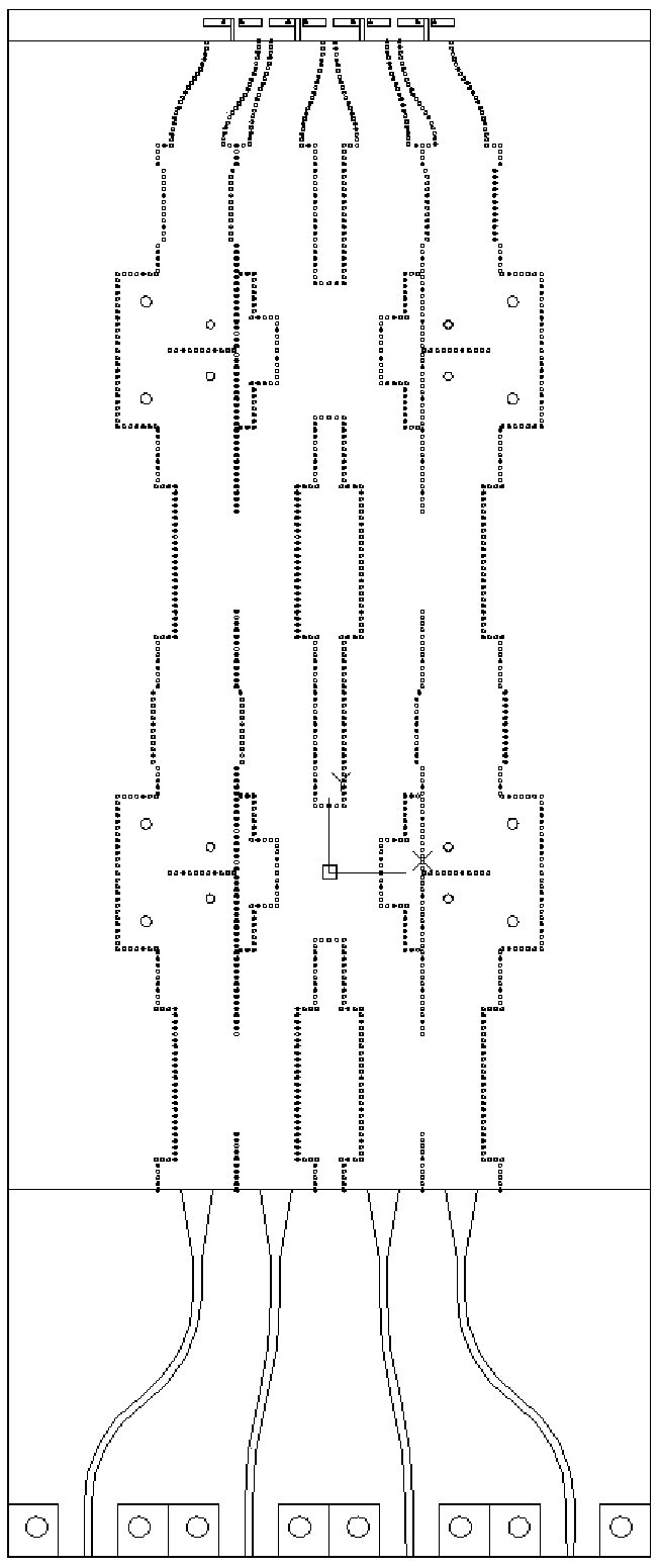
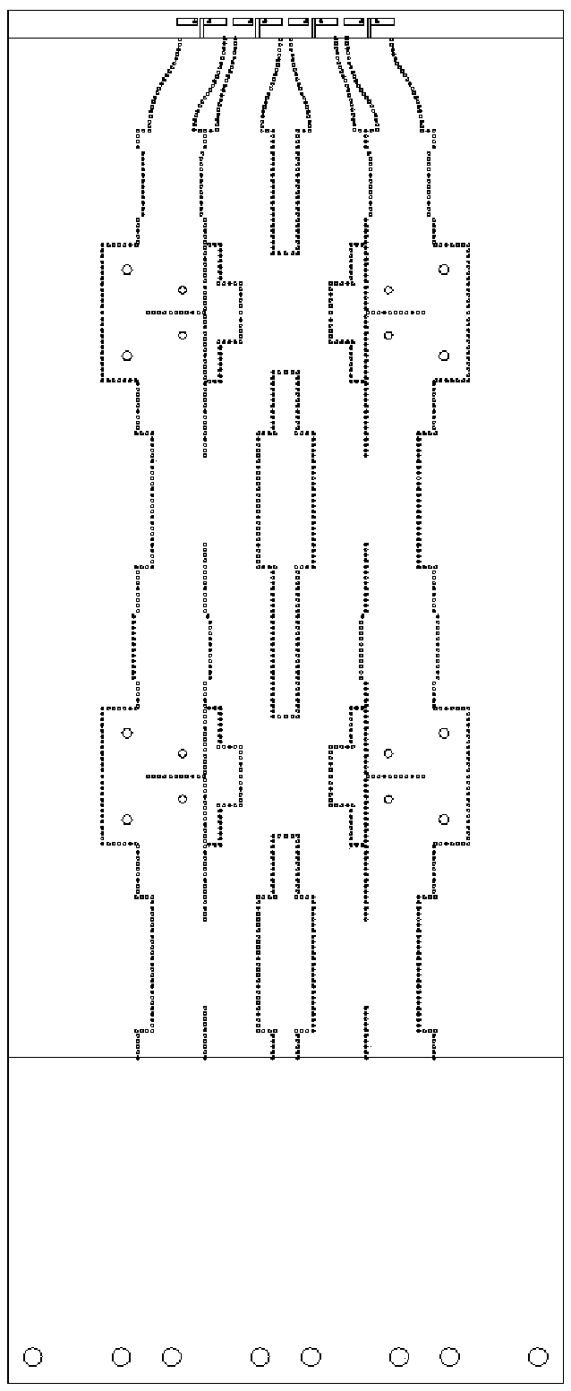
[0026] A millimeter-wave passive multi-beam array device for a mobile terminal and its implementation method, the millimeter-wave passive multi-beam array of the mobile terminal includes a double-sided printed dipole antenna array, and a substrate integrated waveguide feeder Network, passive beamforming network (such as Butler matrix, Rotman lens, etc.), microstrip feed network.

[0027] Specifically, the antenna array includes four double-sided printed dipole antennas, which are connected by metallized through holes and have end-fire characteristics. The bottleneck problem of shielding millimeter wave signals. The invention adopts the substrate integrated waveguide as the feeding structure, and utilizes the double balance characteristic of the substrate integrated wave...


PUM


Abstract

The invention discloses a millimeter wave passive multi-beam array device for a mobile terminal and an implementation method of the millimeter wave passive multi-beam array device; the device is provided with a dipole antenna array with double-sided printing, a feed network formed by a dielectric substrate integrated waveguide, a passive beam forming network and a micro-strip feed network. The millimeter wave passive multi-beam array can also be formed, and the characteristics of low profile, easiness in integration and H-surface wide beam coverage can be achieved; an antenna array is fed through the phase shift characteristics of the different input ports of the passive beam forming network, so that the beam scanning characteristic of the E surface and the multi-beam characteristic can beobtained; and by adoption of the scheme of the three pairs of electric dipole antenna arrays, the three-dimensional space coverage requirement of the terminal equipment over the hemisphere can be met, wherein the main space region meets the double polarization requirement.

Description

technical field [0001] The invention belongs to wireless communication technology, and in particular relates to a millimeter-wave passive multi-beam array device for a mobile terminal and an implementation method thereof. Background technique [0002] In the future wireless communication system, the millimeter wave frequency band has a vast undeveloped spectrum, which can provide support for further increasing the communication rate. Therefore, the millimeter-wave frequency band has received extensive attention from various countries and has become a research focus worldwide. At present, more and more countries and regions have begun to adopt the millimeter-wave frequency band as a candidate frequency band for the fifth-generation mobile communication system. The millimeter-wave frequency band has a lower wavelength, which can make the device miniaturized and facilitate system integration. However, due to the attenuation effect of the atmosphere on electromagnetic waves in ...

Claims


Application Information

Patent Timeline
Patent Type & Authority Applications(China)
IPC IPC(8): H01Q21/08H01Q21/00H01Q9/28H01Q9/04H01Q1/50H01Q1/38H01Q1/24H01Q1/22H01Q21/29
CPCH01Q1/22H01Q1/2258H01Q1/242H01Q1/38H01Q1/50H01Q9/045H01Q9/285H01Q21/0075H01Q21/08H01Q21/293
Inventor 洪伟余超吴凡蒋之浩
Owner SOUTHEAST UNIV
Learn More