Automatic plate material finely cutting system

A precision shearing and sheet metal technology, which is applied in the direction of shearing equipment, shearing devices, and accessories of shearing machines, etc., can solve problems such as inability to cut steel plates, unsmooth adjustment of steel plate positions, and deformation of steel plates during cutting.

Active Publication Date: 2019-04-12
杭州宝伟汽车零部件有限公司
View PDF6 Cites 7 Cited by
  • Summary
  • Abstract
  • Description
  • Claims
  • Application Information

AI Technical Summary

Problems solved by technology

[0004] In order to solve the above problems, the present invention provides an automatic precision shearing system for sheet metal, which can solve the problems that existing steel sheets cannot be positioned when cutting the corners of the steel sheets, the position of the steel sheets cannot be adjusted smoothly, and the steel sheets cannot be differently cut. The cutting of the inclined notch and the deformation of the steel plate can realize the functions of firmly fixing the steel plate and cutting the corner of the steel plate. It can position the steel plate of different sizes, adjust the position of the steel plate smoothly, and can It has the advantages of cutting different slope incisions, no deformation when cutting steel plates, etc.

Method used


Image

  • Automatic plate material finely cutting system
  • Automatic plate material finely cutting system
  • Automatic plate material finely cutting system

Examples


Embodiment Construction

[0027] In order to make the technical means, creative features, goals and effects achieved by the present invention easy to understand, the present invention will be further described below in conjunction with specific illustrations. It should be noted that, in the case of no conflict, the embodiments in the present application and the features in the embodiments can be combined with each other.

[0028] The existing palletizing robot described in this application is mainly composed of the existing public robot and the end picker. The end picker is mainly a vacuum suction cup, and the vacuum suction cup is used as the execution end. Plates that need to be trimmed.

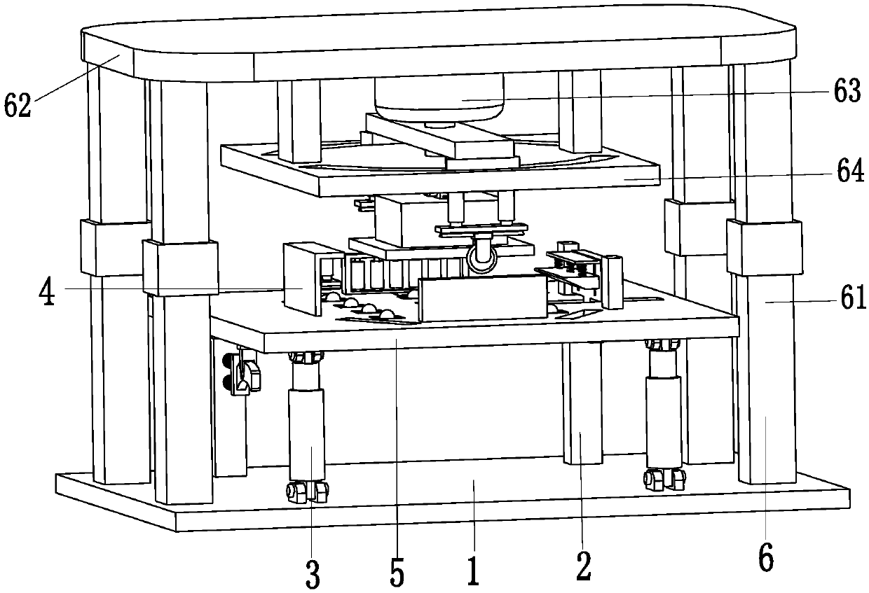
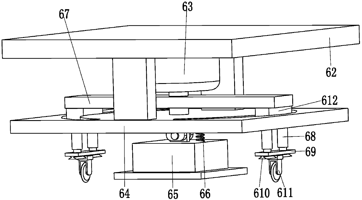
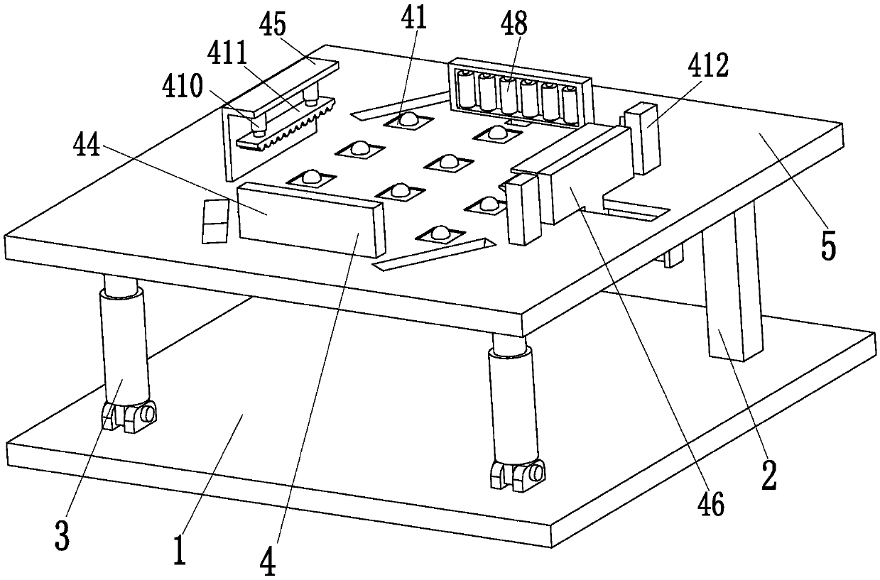
[0029] Such as Figure 1 to Figure 9 As shown, a sheet metal automatic precision shearing system includes a support base plate 1, a support column 2, an angle hydraulic cylinder 3, a positioning device 4, a positioning support plate 5 and a cutting device 6, and the rear end top of the support base plate 1 is The...


PUM


Abstract

The invention relates to an automatic plate material finely cutting system. The automatic plate material finely cutting system comprises a supporting bottom plate, supporting columns, angle hydrauliccylinders, a positioning device, a positioning supporting plate, and cutting devices. The supporting columns are mounted on the top of the rear end of the supporting bottom plate. The rear end of thepositioning supporting plate is mounted on the tops of the supporting columns by hinges. The angle hydraulic cylinders are arranged at the bottom of the front end of the positioning supporting plate.The angle hydraulic cylinders are mounted between the supporting bottom plate and the positioning supporting plate by hinges. Cutting grooves are symmetrically formed in the outer end of the positioning supporting plate. The positioning device is mounted on the positioning supporting plate. The cutting devices are located at the upper end of the positioning supporting plate. The cutting devices are mounted on the top of the outer end of the supporting bottom plate. The automatic plate material finely cutting system can solve the problems that when corners of existing steel plates are cut, thesteel plates with different sizes can not be positioned, steel plate position adjusting is not smooth, steel plate cutting with different cutting edge inclinations can not be achieved, and the steel plates deform during cutting.

Description

technical field [0001] The invention relates to the technical field of full automation of plate shearing processing, in particular to an automatic precision shearing system for plate materials. Background technique [0002] With the increasingly intensified competition in the automobile market, effectively reducing the cost of automobile manufacturing has become a major consideration for various automobile factories. Laser tailor welding of automotive plates can effectively improve the strength of the plates and reduce the cost of the plates. The plates required for laser tailor welding The dimensional accuracy is high, and the sheet material needs to be cut twice before it can be used for tailor welding. At present, the sheet material for laser tailor welding is cut by manual operation of a shearing machine, which has the problems of low work efficiency and poor cutting accuracy. , it is difficult to meet the needs of laser tailor welding. [0003] As a result, the precisi...

Claims


Application Information

Patent Timeline
Patent Type & Authority Applications(China)
IPC IPC(8): B23D19/00B23D33/02
CPCB23D19/00B23D33/02
Inventor 何斌李波
Owner 杭州宝伟汽车零部件有限公司
Why Eureka
Try Eureka