
Cable partial discharge positioning method and system based on active synchronization

A cable partial discharge and active synchronization technology, applied in the direction of measuring electricity, measuring electrical variables, testing dielectric strength, etc., can solve the problems of high price, difficult on-site implementation, and can not fully meet the positioning requirements of cable partial discharge sources, and can achieve on-site Ease of implementation, the effect of eliminating additional errors

Inactive Publication Date: 2019-04-09
HUAINAN POWER SUPPLY CO OF STATE GRID ANHUI ELECTRIC POWER CORPORATIO +2
View PDF5 Cites 6 Cited by
  • Summary
  • Abstract
  • Description
  • Claims
  • Application Information

AI Technical Summary

Problems solved by technology

[0008] (1) Satellite (GPS / BD) timing synchronization, satellite timing requires an external antenna, and for cable partial discharge monitoring equipment that is often installed in tunnels / cable trenches, it is difficult to lay antennas
In addition, the existing GPS / BD timing accuracy is generally at the 10ns level, which cannot fully meet the cable PD source positioning requirements
[0009] (2) The accuracy of optical fiber synchronization is high, which can reach the 1ns level, but optical fiber synchronization requires long-distance optical cables, and it is difficult to implement on-site, and the price is relatively expensive

Method used


Image

  • Cable partial discharge positioning method and system based on active synchronization
  • Cable partial discharge positioning method and system based on active synchronization
  • Cable partial discharge positioning method and system based on active synchronization

Examples


Embodiment Construction

[0022] It should be noted that, in the case of no conflict, the embodiments in the present application and the features in the embodiments can be combined with each other. The present invention will be described in detail below with reference to the accompanying drawings and examples.

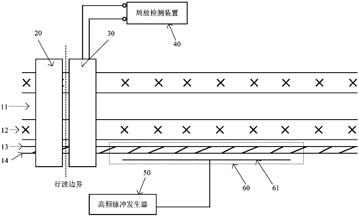
[0023] The synchronization methods of devices at both ends in the existing cable partial discharge source location are: satellite synchronization and optical fiber synchronization. These two methods are difficult to implement on site and the cost is relatively high. In view of the above problems, the present invention proposes a synchronous signal injection method of constructing a coupling capacitor, which is compared with the inductive coupling method. The synchronous signal is injected through the coupling capacitor, the signal attenuation is small, and it is suitable for the partial discharge detection / monitoring system based on the capacitive sensor.

[0024] The present invention propose...


PUM


Abstract

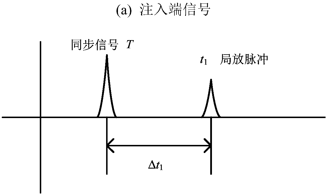
The invention discloses a cable partial discharge positioning method and system based on active synchronization. The method comprises the following steps of: wrapping the outer sheath of the cable with an annular metal plate to form a coupling capacitor; covering both ends of the cable range to be tested with shielding magnetic ring to form a traveling wave boundary; injecting a high frequency pulse into the cable shielding layer as a synchronization signal through a coupling capacitor at one end of the cable range to be detected; extracting a partial discharge pulse signal and a synchronization signal at both ends of the cable range to be detected; and positioning and computing the cable partial discharge source based on the time difference of partial discharge pulse and the synchronization pulse at both ends of the cable range to be detected. The cable partial discharge positioning method and system based on active synchronization use an external annular metal plate to form a coupling capacitor to solve the problem of synchronous injection of the pulse signal, use the time difference between the synchronization signal and the cable partial discharge pulse to complete the local discharge source positioning. Compared with the traditional satellite timing synchronization and fiber synchronization method, it is convenient to implement in the field, and basically eliminates the additional error caused by time synchronization.

Description

technical field [0001] The invention relates to the field of cable partial discharge detection, in particular to a method for locating partial discharge sources of cables based on active synchronization and a system for locating partial discharge sources of cables. Background technique [0002] The cable is affected by electricity, heat and stress during long-term operation, as well as improper operation during construction and installation, which may cause local insulation defects in the cable body and accessories, and partial discharge (referred to as partial discharge). As the cable partial discharge continues, local defects will eventually develop into a breakdown of the insulation as a whole. [0003] At present, domestic and foreign research institutes have carried out a large number of cable partial discharge detection / monitoring researches, and achieved many results. Authoritative organizations such as IEEE believe that partial discharge measurement is an effective ...

Claims


Application Information

Patent Timeline
Patent Type & Authority Applications(China)
IPC IPC(8): G01R31/12
CPCG01R31/1272
Inventor 夏炜唐旭明郭宁明马杰史梦迪韩先国侯传锦施淮生张明帅
Owner HUAINAN POWER SUPPLY CO OF STATE GRID ANHUI ELECTRIC POWER CORPORATIO
Learn More