
Modal test and parameter identification method for single-shaft ball screw feeding mechanical system

A technology of ball screw and mechanical system, which is applied in the field of feed drive experiment testing, can solve the problems that can only be obtained, but it is difficult to completely eliminate the vibration signal pickup of CNC system and servo system, and rotary moving parts, so as to eliminate the influence of electrical links , high precision and wide versatility

Inactive Publication Date: 2019-04-09
XI AN JIAOTONG UNIV
View PDF3 Cites 5 Cited by
  • Summary
  • Abstract
  • Description
  • Claims
  • Application Information

AI Technical Summary

Problems solved by technology

One method is to use the test function of the CNC system of the machine tool to excite the servo motor to obtain the origin frequency response of the motor rotor or the cross-point frequency response of the rotor-worktable. This method requires the CNC or servo of the machine tool on the one hand. The system supports this function. On the other hand, the results obtained by this method are difficult to completely exclude the influence of the CNC system and the servo system, and because the excitation position and signal pickup position are fixed, it is generally difficult to obtain a complete experimental modal set of the feed system.
Another method is to test the feed system through the hammer test. Although this method can eliminate the influence of electrical links, it is difficult to directly use the hammer test because the feed system includes two forms of motion, rotary motion and linear motion. Excite and pick up vibration signals for rotary moving parts, so generally only the origin response at the workbench can be obtained
It can be seen that there is currently a lack of an accurate test method that can directly obtain the origin and cross-point frequency response of each mechanical structure of the ball screw feed system

Method used


Image

  • Modal test and parameter identification method for single-shaft ball screw feeding mechanical system
  • Modal test and parameter identification method for single-shaft ball screw feeding mechanical system
  • Modal test and parameter identification method for single-shaft ball screw feeding mechanical system

Examples


Embodiment Construction

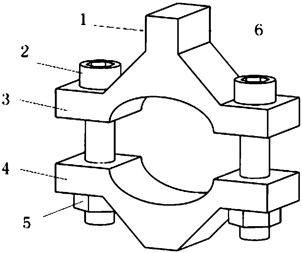
[0027] The present invention will be further described below with reference to the accompanying drawings.

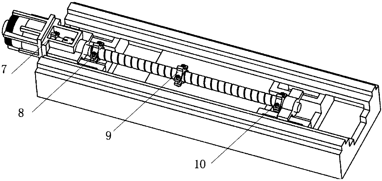
[0028] refer to figure 1 , the auxiliary clamping device that the present invention adopts comprises auxiliary clamping device upper piece 3 and auxiliary clamping device lower piece 4, and auxiliary clamping device upper piece 3 and auxiliary clamping device lower piece 4 are connected by fastening bolt 2, nut 5 , the auxiliary clamping device is used to provide auxiliary functions for exciting and picking up vibrations of rotating parts (such as motor rotors, lead screws, etc.); when in use, loosen the nut 5 on one side of the device, and put the auxiliary clamping device on at the test position of the rotor or lead screw, e.g. figure 2 As shown, the auxiliary clamping device is located at the installation position of the ball screw feeding mechanical system. Installation position 9, installation position 10 of the auxiliary clamping device at the right end of the l...


PUM


Abstract

The invention discloses a modal test and parameter identification method for a single-shaft ball screw feeding mechanical system. Firstly, an auxiliary clamping device is mounted on a rotary motion part in the ball screw feeding mechanical system, an acceleration sensor is arranged, a force hammer is used for carrying out excitation, an excitation signal and an acceleration signal are collected, and an experimental frequency response curve containing the rotary motion part is obtained; then, the experimental frequency response curve is converted, an excitation force is converted into an excitation torque, a tangential displacement is converted into a torsion angle, experimental modal parameter identification is carried out by means of a modal analysis theory, and structural physical parameters of the feeding system are reversely calculated by means of experimental modal parameters; and finally, the influence of the mass and the rotational inertia of the auxiliary clamping device on thestructural physical parameters and the experimental modal parameters of the feeding system is eliminated, and actual physical parameters and modal parameters of the feeding system are obtained. Direct testing of original point and cross point frequency responses of any parts of the mechanical structure of the ball screw feeding system is realized.

Description

technical field [0001] The invention belongs to the technical field of feed drive experiment testing of numerical control machine tools, and in particular relates to a modal test and parameter identification method of a single-axis ball screw feed mechanical system. technical background [0002] At present, there are two main types of feed drive methods for CNC machine tools: direct drive by linear motors and drive by ball screw feed systems. Among them, the ball screw feed system has become one of the most widely used linear feed implementation methods due to its low cost, high rigidity, good impact resistance and anti-interference performance. With the development of technology and the improvement of production demand, the performance requirements of CNC machine tools are getting higher and higher, and the ball screw feed system contains many flexible parts such as flexible parts and dynamic and static joints. The key to the performance of the entire machine tool. The us...

Claims


Application Information

Patent Timeline
Patent Type & Authority Applications(China)
IPC IPC(8): G01M13/02G01M13/028G01M7/08
CPCG01M7/08G01M13/02G01M13/028
Inventor 赵万华张伟张星张俊
Owner XI AN JIAOTONG UNIV
Learn More