Log slotting device
A technology of log and pressing device, which is applied in the direction of slotting machine, wood processing equipment, manufacturing tools, etc., can solve the problems of increasing workload, increasing labor intensity, and getting stuck into people's hands, so as to reduce labor intensity and reduce workload effect
- Summary
- Abstract
- Description
- Claims
- Application Information
AI Technical Summary
Problems solved by technology
Method used
Image

Examples
Embodiment 1
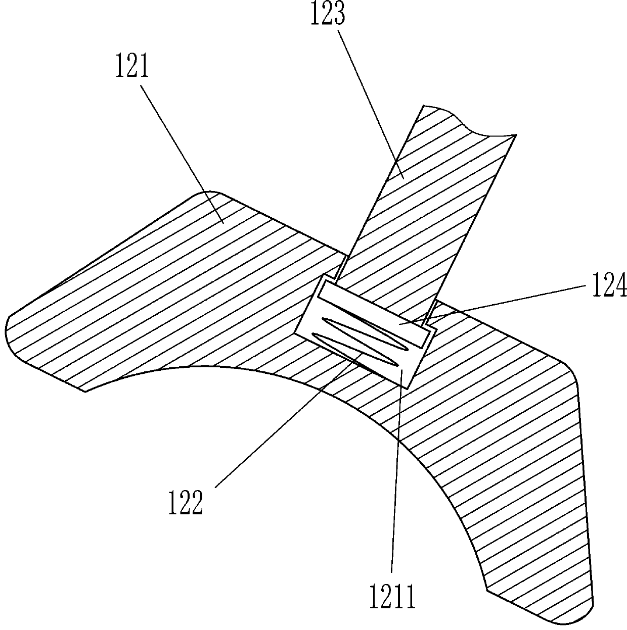
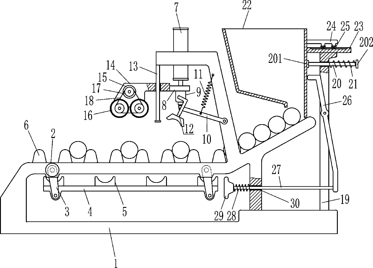
[0015] A log notching device, such as Figure 1-2 As shown, it includes a frame 1, a first motor 2, a first swing lever 3, a bracket 4, a bracket 5, a bump 6, a cylinder 7, a flat panel 8, an electric drill 9, a second swing lever 10, and a tension spring 11 And pressing device 12, the left part of frame 1 front side is equipped with the first motor 2 that can drive the first swing bar 3 to rotate, and frame 1 is connected with the first motor 2 by the mode of bolt connection, and the rear of frame 1 The left and right sides of the lower part of the side are rotatably connected with a first swing lever 3, the rear end of the output shaft of the first motor 2 passes through the front wall of the frame 1, and the rear end of the output shaft of the first motor 2 is connected to the left first swing. The rod 3 is fixedly connected, and the bottoms of the left and right first swing rods 3 are connected in a rotating manner with a supporting bracket 4. The top of the bracket 4 is e...
Embodiment 2
[0017] A log notching device, such as Figure 1-2 As shown, it includes a frame 1, a first motor 2, a first swing lever 3, a bracket 4, a bracket 5, a bump 6, a cylinder 7, a flat panel 8, an electric drill 9, a second swing lever 10, and a tension spring 11 And pressing device 12, the left part of frame 1 front side is equipped with the first motor 2 that can drive the first swing bar 3 to rotate, and the left and right sides of frame 1 inner rear side lower part are all rotatably connected with the first swing bar 3. The rear end of the output shaft of the first motor 2 passes through the front wall of the frame 1, the rear end of the output shaft of the first motor 2 is fixedly connected to the first swing rod 3 on the left, and the lower parts of the left and right first swing rods 3 The bracket 4 that plays a supporting role is rotatably connected between them, the top of the bracket 4 is equipped with a plurality of brackets 5 that can move the logs, and the front and re...
Embodiment 3
[0020] A log notching device, such as Figure 1-2 As shown, it includes a frame 1, a first motor 2, a first swing lever 3, a bracket 4, a bracket 5, a bump 6, a cylinder 7, a flat panel 8, an electric drill 9, a second swing lever 10, and a tension spring 11 And pressing device 12, the left part of frame 1 front side is equipped with the first motor 2 that can drive the first swing bar 3 to rotate, and the left and right sides of frame 1 inner rear side lower part are all rotatably connected with the first swing bar 3. The rear end of the output shaft of the first motor 2 passes through the front wall of the frame 1, the rear end of the output shaft of the first motor 2 is fixedly connected to the first swing rod 3 on the left, and the lower parts of the left and right first swing rods 3 The bracket 4 that plays a supporting role is rotatably connected between them, the top of the bracket 4 is equipped with a plurality of brackets 5 that can move the logs, and the front and re...
PUM
 Abstract
Description
Claims
Application Information
 - R&D
- Intellectual Property
- Life Sciences
- Materials
- Tech Scout
- Unparalleled Data Quality
- Higher Quality Content
- 60% Fewer Hallucinations
Browse by: Latest US Patents, China's latest patents, Technical Efficacy Thesaurus, Application Domain, Technology Topic, Popular Technical Reports.
© 2025 PatSnap. All rights reserved.Legal|Privacy policy|Modern Slavery Act Transparency Statement|Sitemap|About US| Contact US: help@patsnap.com