Double-ended input A+B type LED fluorescent lamp circuit
A LED fluorescent lamp, double-terminal input technology, applied in the direction of light source, electric light source, electrical components, etc., can solve the problems that cannot meet the requirements of luminous brightness
- Summary
- Abstract
- Description
- Claims
- Application Information
AI Technical Summary
Problems solved by technology
Method used
Image
Examples
Embodiment 1
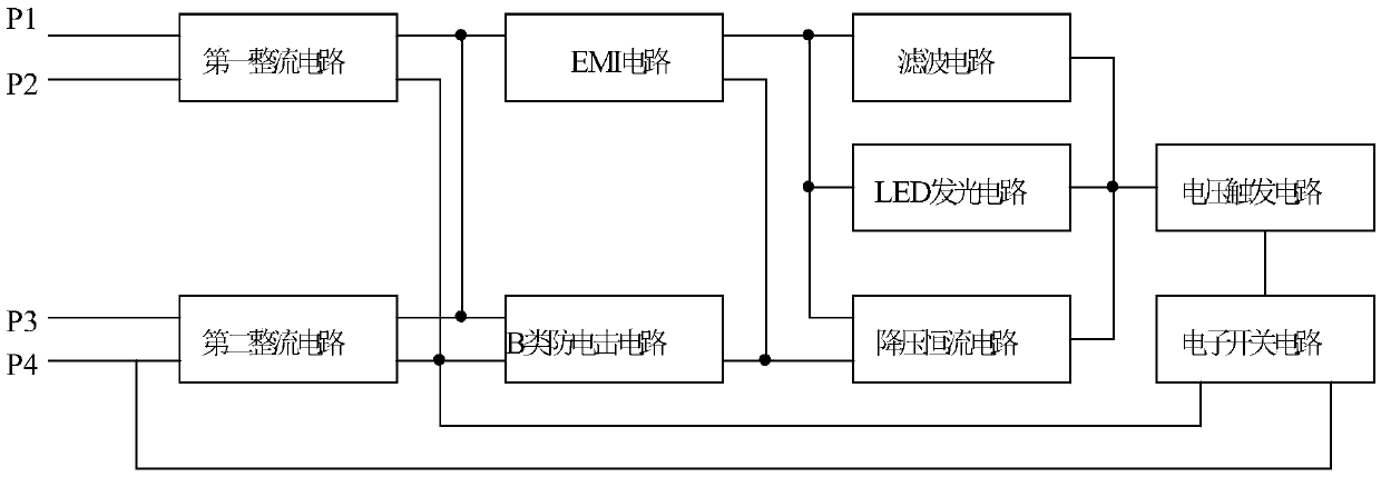
[0027] Embodiment one: if image 3 As shown, a dual-terminal input A+B class LED fluorescent lamp circuit includes a first rectifier circuit, a second rectifier circuit, an EMI circuit, an LED lighting circuit, a filter circuit, a class B anti-shock circuit and a voltage trigger circuit, the first The rectification circuit and the second rectification circuit respectively have a live line input terminal, a neutral line input terminal, an output terminal and a ground terminal; the EMI circuit has an input terminal, an output terminal and a ground terminal; Negative pole, Class B anti-shock circuit has detection terminal, output terminal and ground terminal, the output terminal of the first rectification circuit, the output terminal of the second rectification circuit, the detection terminal of Class B anti-electric shock circuit and the input terminal of the EMI circuit are connected, EMI The ground terminal of the circuit is connected to the output terminal of the class B anti...
Embodiment 2
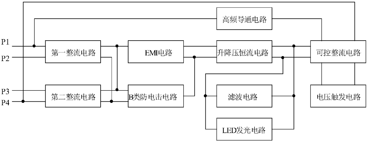
[0028] Embodiment 2: This embodiment is basically the same as Embodiment 1, the difference is:
[0029] Such as Figure 4 As shown, in this embodiment, the buck-boost constant current circuit includes a first capacitor C1, a second capacitor C2, a first diode D1, a second diode D2, a first resistor R1, a second resistor R2, a first Three resistors R3, the first inductor L1 and the first integrated circuit chip U1, the model of the first integrated circuit chip U1 is MT7845, the first diode D1 and the second diode D2 are high-frequency rectifier diodes, the first integrated circuit The 5th pin of the circuit chip U1 is connected to the 6th pin and its connecting end is the input end of the buck-boost constant current circuit, the anode of the first diode D1 is the negative output end of the buck-boost constant current circuit, and the second and second diodes are connected to each other. The negative pole of the pole tube D2 is the positive output terminal of the buck-boost co...
PUM
 Abstract
Description
Claims
Application Information
 - Generate Ideas
- Intellectual Property
- Life Sciences
- Materials
- Tech Scout
- Unparalleled Data Quality
- Higher Quality Content
- 60% Fewer Hallucinations
Browse by: Latest US Patents, China's latest patents, Technical Efficacy Thesaurus, Application Domain, Technology Topic, Popular Technical Reports.
© 2025 PatSnap. All rights reserved.Legal|Privacy policy|Modern Slavery Act Transparency Statement|Sitemap|About US| Contact US: help@patsnap.com


