A grid-connected current control method applied to lcl type rectification feedback unit

A current control and feedback unit technology, applied in the direction of converting AC power input to DC power output, electrical components, output power conversion devices, etc., can solve the gain limitation of grid-connected current control loop, increase the difficulty of system stability control, Increase the additional loss of the system and other problems to achieve the effect of alleviating the impact, improving the stability margin, and increasing the gain

Active Publication Date: 2020-05-22
XIAN UNIV OF TECH
View PDF4 Cites 0 Cited by
  • Summary
  • Abstract
  • Description
  • Claims
  • Application Information

AI Technical Summary

Problems solved by technology

[0004] However, because it is a third-order system, the LCL filter has resonance characteristics, which makes the control of the system more complicated and more sensitive to harmonics, which increases the difficulty of system stability control, so it is necessary to introduce a damping control method to suppress the resonance peak. Impact
There are two types of damping control methods: passive damping control and active damping control. Passive damping control is to connect resistors in series or in parallel in the capacitor branch, and increase the system damping coefficient to suppress the resonance peak. However, this control method increases The extra loss of the system reduces the system efficiency, so the active damping control method is often used in systems with high efficiency requirements, that is, the damping coefficient of the system is increased by designing the controller
[0005] The existing active damping control method has limitations in the gain of the grid-connected current control loop

Method used


Image

  • A grid-connected current control method applied to lcl type rectification feedback unit
  • A grid-connected current control method applied to lcl type rectification feedback unit
  • A grid-connected current control method applied to lcl type rectification feedback unit

Examples


Embodiment Construction

[0051] The present invention will be described in detail below in conjunction with the accompanying drawings and specific embodiments.

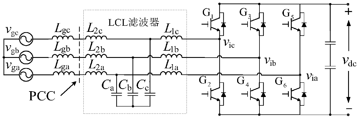
[0052] The present invention is a grid-connected current control method applied to an LCL rectifier feedback unit. The AC side current control system includes a main circuit part and a control circuit part. The topology of the main circuit is as follows: figure 1 As shown, the actual power grid system is inductive, and L in the figure g is the grid-side equivalent inductance, then the actual sampling point of the grid voltage is the common coupling point PCC, and the common coupling point voltage v pcc After the LCL filter, and then the rectifier output DC voltage V dc , the DC voltage is filtered by a capacitor to obtain the final output voltage, as can be seen from Figure 1, L 1 is the grid-connected side inductance, and the control object of the present invention is L 1 The current on the grid, that is, the grid-connected current i L1 ...


PUM


Abstract

The invention discloses a grid-connected current control method applied to an LCL type rectifying feedback unit. The method comprises a step of converting a network voltage and an AC side current in athree-phase stationary coordinate system into a network voltage and an AC side current in a two-phase stationary coordinate system and obtaining a predicted current by a current prediction link, a step of allowing given active current and reactive current to pass through a transformation matrix to obtain current given values in the two-phase stationary coordinate system, and a step of taking thepredicted current and an error value of the current given values as an input of a new control link, adding an output of the new control link and a voltage of a common coupling point through a feedforward coefficient to obtain loop output signals, obtaining a control output signal under the three-phase stationary coordinate system through the transformation of the transformation matrix, generatinga modulated signal through DC bus voltage decoupling, and obtaining a PWM waveform by a modulator. According to the invention, the gain of a grid-connected current control loop is improved, the resonance peak is effectively suppressed, and the influence of grid voltage disturbance and DC bus voltage fluctuation on the stability of the system is alleviated.

Description

technical field [0001] The invention belongs to the technical field of grid-connected current control methods, and relates to a grid-connected current control method applied to an LCL type rectification feedback unit. Background technique [0002] Nowadays, power electronic converter technology continues to develop, and power electronic devices are gradually updated. The rectification unit of the traditional frequency conversion control system uses an uncontrollable diode rectification element, the current is conducted in one phase, and there is no energy feedback. It needs to be equipped with a braking unit. The DC side voltage is uncontrollable, and the power supply voltage cannot be lower than the rated voltage of the motor. The rectification unit of the AFE frequency conversion control system adopts active controllable IGBT rectification elements, which can be controlled on and off, the current flows in both directions, and no braking unit is required. The PWM control is...

Claims


Application Information

Patent Timeline
Patent Type & Authority Patents(China)
IPC IPC(8): H02M7/72H02M7/797H02M1/12
CPCH02M1/126H02M7/72H02M7/797
Inventor 张琦赵双双沈鸿孙向东安少亮任碧莹马高峰王闻程
Owner XIAN UNIV OF TECH
Why Eureka
Try Eureka