
Vibration isolation system for floating raft with resonance peak suppression

A vibration isolation system and resonance peak technology, applied in non-rotational vibration suppression, ship propulsion, ship parts, etc., can solve the problems of weakened vibration isolation effect, no vibration isolation effect, vibration amplification, etc., and achieve the effect of excellent vibration isolation effect.

Active Publication Date: 2015-10-07
ZHEJIANG UNIV OF TECH
View PDF6 Cites 0 Cited by
  • Summary
  • Abstract
  • Description
  • Claims
  • Application Information

AI Technical Summary

Problems solved by technology

However, there are three obvious resonance peaks on the acceleration frequency response curve, especially the existence of the first two resonance peaks, which has an extremely adverse effect on the vibration isolation performance of the floating raft vibration isolation system. Within a certain range, the vibration isolation effect is greatly weakened. What's more, sometimes in a certain range of frequencies corresponding to the two resonance peaks, instead of the vibration isolation effect, the vibration will be amplified.

Method used


Image

  • Vibration isolation system for floating raft with resonance peak suppression
  • Vibration isolation system for floating raft with resonance peak suppression
  • Vibration isolation system for floating raft with resonance peak suppression

Examples


Embodiment

[0020] The floating raft vibration isolation system diagram of the resonance peak suppression of the present invention is as follows Figure 4 , the first switch-type damper is installed between the unit and the raft body of the floating raft vibration isolation system, and the second switch-type damper is installed between the unit and the foundation of the floating raft vibration isolation system. For the relevant parameters of the system, see Table 1.

[0021] Table 1 Relevant parameters of the embodiment of the floating raft vibration isolation system for resonance peak suppression

[0022]

[0023] The acceleration frequency response curve of the floating raft vibration isolation system unit transmitted to the foundation by the harmonic peak suppression is as follows Figure 5 shown.

[0024] When the system is not equipped with a damper, it is equivalent to that the switch-type damper 6 is always closed, and the switch-type damper 7 is always closed (that is, both t...


PUM


Abstract

The invention relates to a floating-raft vibration isolation system with suppressed resonant peaks. The floating-raft vibration isolation system comprises a unit and a raft. A first switch-type damper is arranged between the unit and the raft. A second switch-type damper is arranged between the unit and a base.

Description

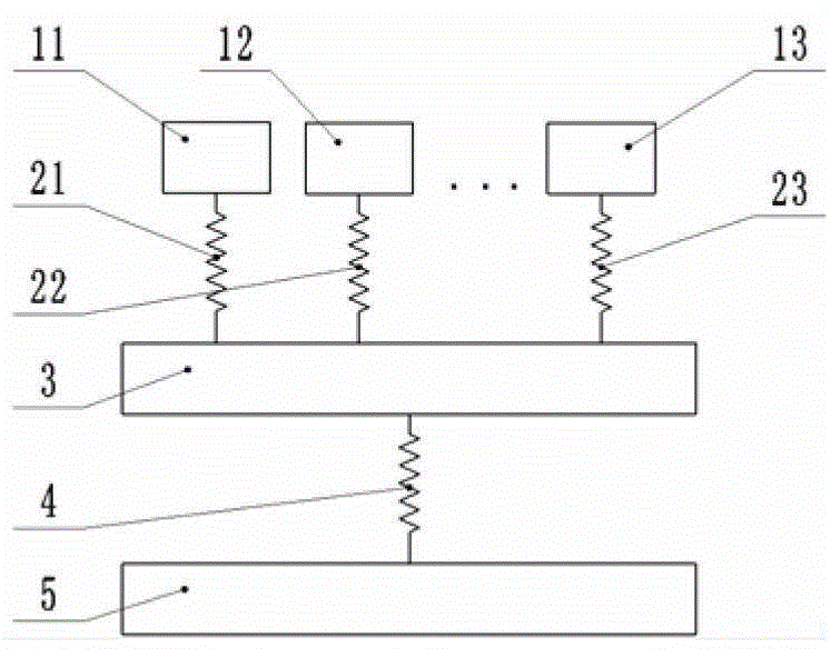
technical field [0001] This patent relates to a vibration isolation device for ship power units. Background technique [0002] In the design and manufacture of modern ships, more and more attention is paid to the vibration control of ship power units, especially on military ships and submarines. At present, the most effective technology is the vibration isolation technology of floating rafts. [0003] figure 1 is the mechanical model of the floating raft vibration isolation system, figure 1 The middle power unit 11, the power unit 12, and the power unit 13 are the most important sources of vibration. To better isolate the vibration transmitted from the power unit 1 to the foundation 5, a raft 3 can be added between the unit and the foundation, and each unit All are supported on the raft body 3 by the spring 2, and the raft body 3 is supported on the foundation by the spring 4 again. If we only discuss the case of only one power unit, it can be simplified as figure 2 mod...

Claims


Application Information

Patent Timeline
Patent Type & Authority Patents(China)
IPC IPC(8): F16F15/02B63H21/30
Inventor 翁泽宇王辉卢波丁红钢游红武
Owner ZHEJIANG UNIV OF TECH
Learn More