
Preparation method of speckle and characterization method for material microdomain deformation

A technology of speckle and speckle particles, which is applied in the field of deformation measurement and photomechanics, can solve the problems that EBSD and DIC cannot be effectively combined, and achieve the effect of good contrast, appropriate thickness and uniform distribution

Active Publication Date: 2019-04-05
SOUTHWEST JIAOTONG UNIV
View PDF2 Cites 7 Cited by
  • Summary
  • Abstract
  • Description
  • Claims
  • Application Information

AI Technical Summary

Problems solved by technology

[0006] The main purpose of the present invention is to provide a speckle preparation method and a characterization method for material micro-region deformation, so as to solve the problem that EBSD and DIC cannot be effectively combined in the prior art

Method used


Image

  • Preparation method of speckle and characterization method for material microdomain deformation
  • Preparation method of speckle and characterization method for material microdomain deformation
  • Preparation method of speckle and characterization method for material microdomain deformation

Examples


Embodiment 6

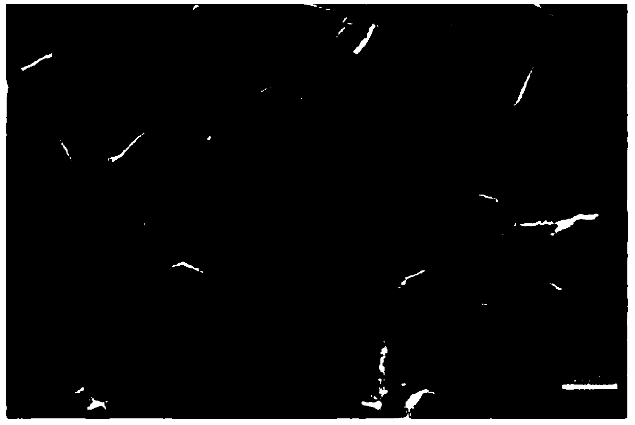
[0074] Examples 6-10 are comparative examples of Example 3. The difference is that the speckle particle powders used in Examples 6-10 are silica, silver powder, aluminum powder, tungsten powder, and alumina with a mass ratio of 1:1. Mixed powder of silica. It has been verified that the degree of speckle interference: Example 3<Example 10<Example 6<Examples 7-9, indicating that oxide powder is more suitable for speckle particle powder than simple metal powder, and oxide is oxidized Aluminum is the most preferred.

Embodiment 11

[0075] Example 11 is a comparative example of Example 1, and the difference is that the particle size of the speckle particle powder of Example 11 is 10 nm. It has been verified that the degree of speckle interference in Example 11 is significantly higher than that in Example 1, indicating that the particle size of the speckle particles cannot be too small, or the interference may be aggravated due to agglomeration.

Embodiment 12

[0076] Example 12 is a comparative example of Example 5, and the difference is that the particle size of the speckle particle powder of Example 12 is 100 nm. It has been verified that the degree of speckle interference in Example 12 is significantly higher than that in Example 5, indicating that the particle size of the speckle particle powder cannot be too large, or whether the interference may be aggravated due to the excessive particle size.


PUM

PropertyMeasurementUnit
Granularityaaaaaaaaaa

Abstract

The invention discloses a preparation method of speckle and a characterization method for material microdomain deformation. The preparation method of the speckle comprises the following steps that (1)nanometer-sized speckle particle powder is prepared into a suspension; (2) after the suspension is subjected to standing for a period of time, an upper mother clear solution is taken for centrifugation to obtain a child clear solution; and (3) a substrate to be tested is placed in the child clear solution to enable speckle particle powder in the child clear solution to adhere to the surface of the substrate to be tested, and after drying, the speckle is prepared on the surface of the substrate to be tested. The characterization method for the material microdomain deformation comprises the following steps that (1) first the speckle is prepared on the surface of the substrate to be tested by using the preparation method of the speckle; (2) an initial SEM photograph and initial EBSD data ofthe substrate to be tested are obtained; (3) external force loading is performed on the substrate to be tested; (4) a deformation SEM photograph and deformation EBSD data of the substrate to be testedafter the deformation are obtained; and (5) the initial SEM photograph and the deformation SEM photograph are analyzed to obtain a strain field pattern. According to the preparation method of the speckle and the characterization method for the material microdomain deformation, a scanning electron microscope is successfully applied to a DIC experimental method.

Description

Technical field [0001] The present invention relates to the technical field of photometry mechanics and deformation measurement, in particular to a method for preparing speckles and a method for characterizing deformation of micro-regions of materials. Background technique [0002] With the development of modern materials science, the microscopic characterization of the mechanical behavior of materials has become a very important issue in the fields of materials science and solid mechanics. EBSD technology, as an analysis method that has developed rapidly in recent years, can analyze the grain size, grain orientation, and texture of material crystals. Since the EBSD technology is based on electron diffraction imaging, it has certain limitations. It cannot provide an intuitive and accurate measurement of the displacement and strain of the material at the mesoscopic scale during the deformation process. Therefore, the measurement of the displacement and strain of the material in t...

Claims


Application Information

Patent Timeline
IPC IPC(8): G01N23/20008G01N23/20058G01N23/2251G01B15/06
CPCG01B15/06G01N23/2005G01N23/20058G01N23/2251
Inventor 罗胜年李旭哲李超卢磊范端
Owner SOUTHWEST JIAOTONG UNIV
Learn More