
Laser light beam uniformity attenuator

A laser beam and attenuator technology, which is applied in the field of strong laser power density and large multiple quantitative attenuation sampler, can solve the problems that it is difficult to meet the attenuation requirements of high spatial resolution arrays, affect the consistency of laser measurement, and have large differences in attenuation coefficients. Compact structure, good attenuation coefficient consistency, convenient replacement and maintenance

Active Publication Date: 2019-04-05
NORTHWEST INST OF NUCLEAR TECH
View PDF9 Cites 2 Cited by
  • Summary
  • Abstract
  • Description
  • Claims
  • Application Information

AI Technical Summary

Problems solved by technology

The disadvantage of the above-mentioned integrating sphere structure attenuator is that since the integrating sphere attenuator has an asymmetric structure, the sampling entrance hole and the exit hole are located on both sides of the integrating sphere. Large-angle laser attenuation can only be achieved with an included angle between positions, and the attenuator adopts a spherical or hemispherical shape, and the structure is not compact, so it is difficult to meet the attenuation requirements of high spatial resolution array detection
[0005] Authorized patent ZL 201410279528.7 discloses an attenuation sampling device for high-energy laser incident at a large angle, including a straight sampling hole, an exit hole and a cylindrical cavity. The cylindrical cavity is filled with granular optical body scattering materials, which can realize Large-angle attenuation sampling, but the problem is that when filling the cavity with optical body scattering material, the filling density is prone to inconsistency, resulting in a large difference in the attenuation coefficients of different attenuators on the same measurement target board, which affects the consistency of laser measurement. sex

Method used


Image

  • Laser light beam uniformity attenuator
  • Laser light beam uniformity attenuator
  • Laser light beam uniformity attenuator

Examples


Embodiment 1

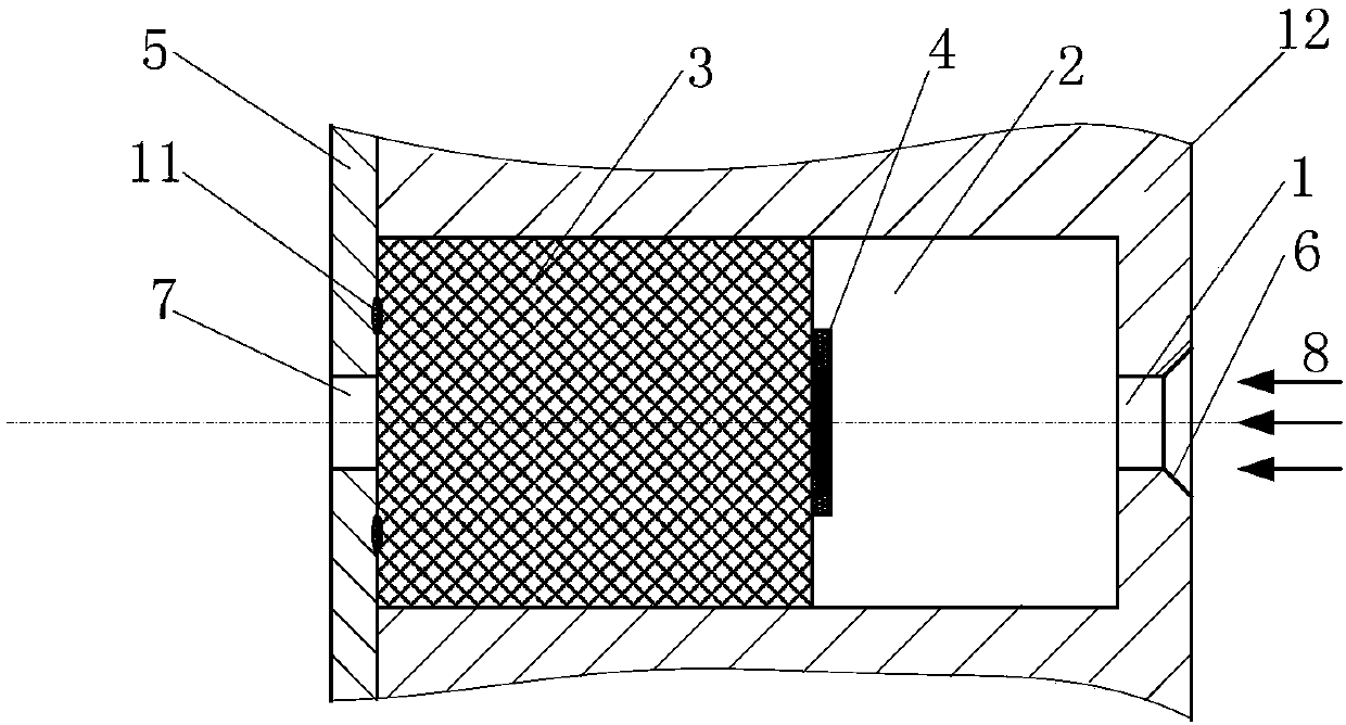
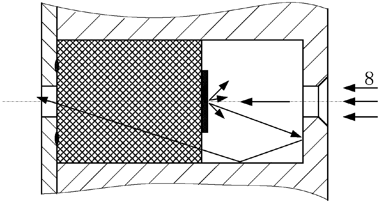
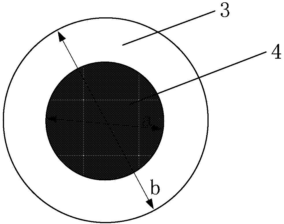
[0033] Such as Figure 1 to Figure 4 As shown, a kind of laser beam homogenization attenuator of the present invention comprises sampling entrance hole 1, attenuation cavity 2 and exit hole 7 that are arranged successively along the laser incident direction, and attenuation cavity 2 is a cavity, and its interior is close to exit hole 7 One end is fixed with a transmissive body 3, the transmissive body 3 is made of white sapphire or quartz glass, which has a high transmittance to the measured laser, and its transmittance is greater than 98%; the middle part of the front surface of the transmissive body 3 is facing the position of the sampling entrance hole 1 A diffuse reflective film 4 with high reflectivity to laser light is arranged at the place, so that the front surface of the transmissive body 3 forms a image 3 Annular clear window shown. image 3 The diameter of the diffuse reflection film 4 is a, and the diameter of the front surface of the transmissive body 3 is b.

...

Embodiment 2

[0038] Such as Figure 5 As shown, this embodiment provides a split attenuator solution. Figure 5 For the structure of fixed attenuation coefficient, the sampling exit hole 7 is set on the fixed bottom plate 5, the attenuation cavity 2 is set in the casing 13, the casing 13 is connected on the fixed bottom plate 5 through the thread 10, and the cavity of the attenuation cavity 2 is provided with The retaining ring 9 that fixes the transparent body 3 relies on the retaining ring to fix the position of the transparent body 3 .

Embodiment 3

[0040] This embodiment provides a split-type attenuator solution with adjustable attenuation coefficient. According to theoretical simulation analysis, the attenuation coefficient of the attenuator mainly depends on the cavity length L, the reflectivity of the inner cavity, and the diameter a of the diffuse reflection film 4 and the transmission The ratio between the surface diameter b of the body 3, so under the condition of the basic structure size and parameter setting, the adjustment of the attenuation coefficient can be easily realized by adjusting the length L of the cavity.

[0041] Such as Figure 6 As shown, the sampling exit hole 7 is set on the fixed bottom plate 5, the attenuation cavity 2 is set in the casing 13, the casing 13 is connected to the fixed bottom plate 5 through the thread 10, and the transmissive body 2 is bonded and fixed in the inner cavity of the attenuation cavity 2 , the beam homogenization attenuator can adjust the length L of the internal cavi...


PUM


Abstract

The invention provides a laser light beam uniformity attenuator. The laser light beam uniformity attenuator comprises an attenuation chamber; the attenuation chamber is a hollow seal chamber, diffusereflection surface treatment is applied on the inner wall of the attenuation chamber, and thus a diffuse reflection layer is formed; a sampling in-emit hole and out-emit hole are coaxially formed in the attenuator relative to the two ends, a transmission body capable of highly transmitting a laser light is fixed to the end, close to the out-emit hole, of the inner part of the attenuation chamber,a diffuse reflection film applying high reflectance to the laser light is arranged on the position, directly opposite to the sampling in-emit hole, on the surface of the transmission body, and the diameter of the diffuse reflection film is larger than the diameter of the sampling in-emit hole. The laser light beam uniformity attenuator has characteristics that the structure is compact, processingis convenient, and attenuation coefficient uniformity of different attenuators is good, and the problems that the spatial size of a traditional integrating sphere body is large, and laser light parameter measuring of high spatial resolution cannot be achieved when a two-dimensional array is configured are solved.

Description

technical field [0001] The invention relates to a high-energy laser beam homogenization attenuator, in particular to a high-power laser power density large multiple quantitative attenuation sampler. Background technique [0002] In the measurement of high-energy laser parameters, it is necessary to obtain the spatiotemporal distribution of laser light intensity. Since the laser power density at the test position is generally high, reasonable attenuation is required to detect it with a photodetector array arranged in an area array. [0003] At present, the commonly used optical attenuation methods mainly include the filter attenuation method and the integrating sphere attenuation method, that is, an optical attenuator is added in front of each detector to attenuate the power of the laser to within the detectable range of the detector. Because the attenuation coefficient of the filter is difficult to accurately calibrate when the filter is attenuated by a large multiple, the r...

Claims


Application Information

Patent Timeline
Patent Type & Authority Applications(China)
IPC IPC(8): G01J1/04
CPCG01J1/0418
Inventor 王振宝吴勇陈绍武武俊杰王飞张磊杨鹏翎冯国斌
Owner NORTHWEST INST OF NUCLEAR TECH
Learn More