
Forming device

A molding device and molding part technology, which can be applied to household appliances, other household appliances, flat products, etc., can solve the problems of poor optical performance, equipment quality degradation, and uneven thickness of film materials.

Active Publication Date: 2021-01-29
INTERFACE TECH CHENGDU CO LTD +2
View PDF5 Cites 0 Cited by
  • Summary
  • Abstract
  • Description
  • Claims
  • Application Information

AI Technical Summary

Problems solved by technology

[0003] In the existing jig, when the pressure is applied to the film material from the side away from the jig, the stress of the film material corresponding to the edge of the forming area is relatively strong, causing the film material to be stretched and deformed. Derived from the changes in optical properties and material thickness of thin film materials, such as deterioration of optical properties, uneven thickness of thin film materials, etc., the above problems will lead to the final target products of thin film materials, which are applied to VR equipment, AR equipment, wearable The quality of equipment such as computers is degraded

Method used

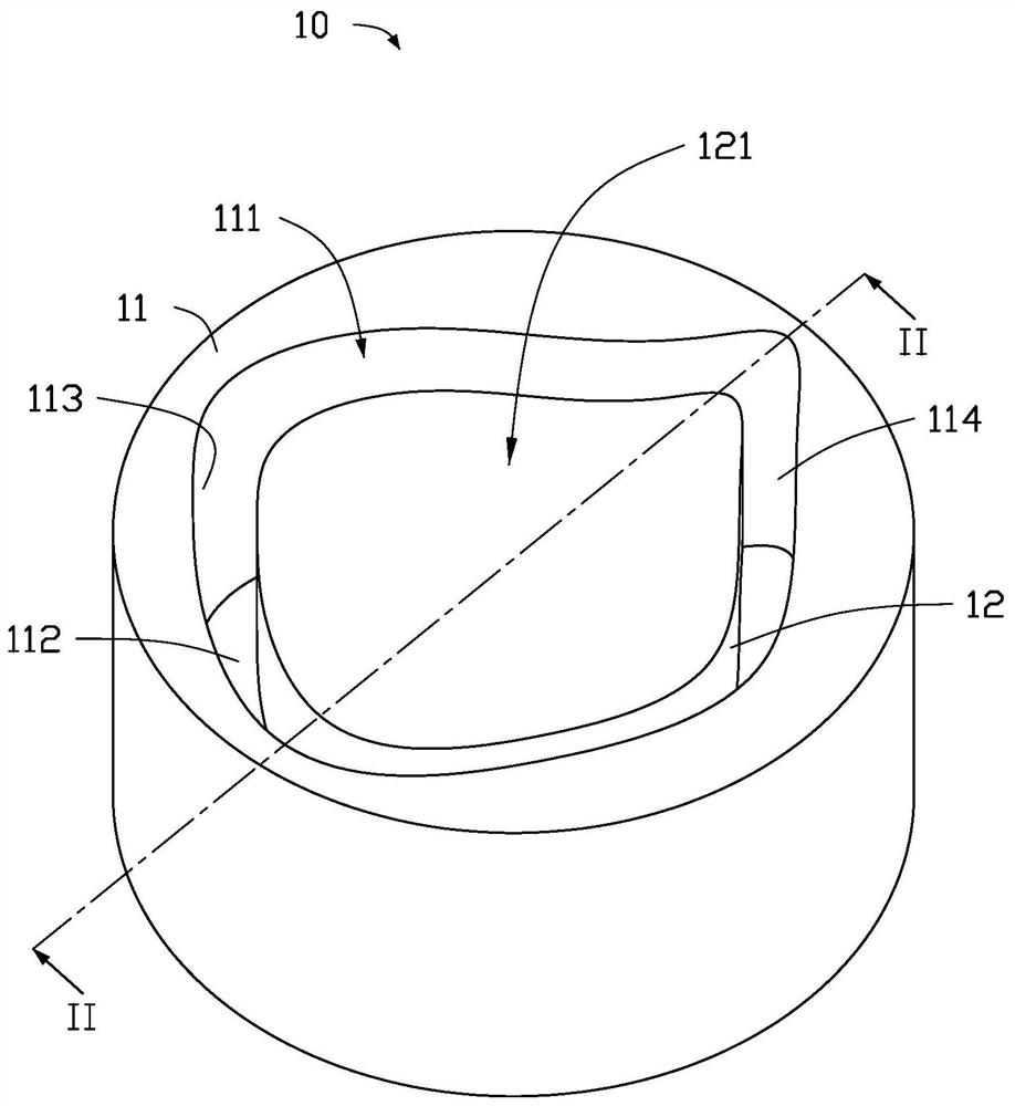
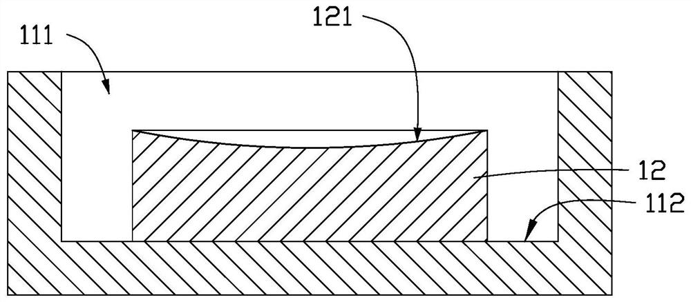

Image

  • Forming device
  • Forming device
  • Forming device

Examples


Embodiment 1

[0018] see figure 1 , the molding device 10 provided in this embodiment includes a bearing part 11 and a molding part 12 combined on the bearing part 11 .

[0019] like figure 1 As shown, a groove 111 is disposed on the carrying portion 11, and the groove 111 is used for accommodating the product to be formed. The groove 111 has a bottom wall 112 , a side wall 113 connected to the bottom wall 112 and an opening 114 away from the bottom wall 112 . The forming portion 12 is disposed on the bottom wall 112 of the groove 111 , and the forming portion 12 is accommodated in the groove 111 . The forming portion 12 is spaced apart from the sidewall 113 of the groove 111 .

[0020] In this embodiment, the carrying part 11 and the forming part 12 are integrally formed, and the integrated forming methods may include but not limited to: 3D printing, injection molding, and the integrated forming method is more efficient. In another embodiment, the forming part 12 is combined with the b...


PUM


Abstract

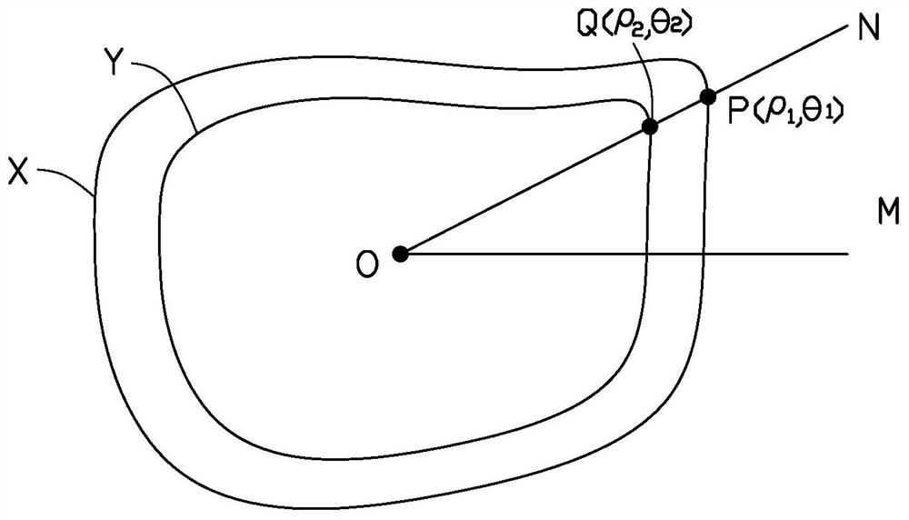
The invention provides a forming device, comprising: a bearing part, a groove is arranged on the bearing part, the groove has a bottom wall and a side wall connected with the bottom wall; and a forming part, the forming part Set on the bottom wall and spaced from the side wall, the forming part has a top surface away from the bottom wall, the top surface is used to carry the product to be formed; the opening profile of the groove is the same as The contours of the edges of the top surface are the same. The molding device provided by the present invention, by setting the contour of the opening of the groove of the molding part to be the same as the contour of the edge of the top surface of the molding part, helps to improve the stress on the film material during the thermoplastic molding process, which causes the optical properties of the film material to be affected. The problem.

Description

technical field [0001] The invention relates to the field of tooling fixtures, in particular to a forming device. Background technique [0002] At present, VR (Virtual Reality, Virtual Reality) equipment, AR (Augmented Reality, Augmented Reality) equipment, wearable computers, etc. generally need to attach optical films, and the above-mentioned optical films are generally completed by thermocompression molding. Take the process of thermoforming to form an optical film as an example, especially when forming an optical film with a curved surface. In the thermoforming process, the film material needs to be placed on a thermoforming jig. area, the profile of the forming area is the same as the target product profile. Apply pressure to the film material from the side away from the jig to make the film material finally form the target product. [0003] In the existing jig, when the pressure is applied to the film material from the side away from the jig, the stress of the film m...

Claims


Application Information

Patent Timeline
Patent Type & Authority Patents(China)
IPC IPC(8): B29C51/18B29C51/30B29L7/00
CPCB29C51/18B29C51/30B29L2007/00
Inventor 周佩吟
Owner INTERFACE TECH CHENGDU CO LTD
Learn More