Oxygen reduction catalyst, and preparation method and application thereof
A technology of catalyst and oxygen element, applied in the field of electrochemical catalysis, can solve the problems of small Pt precious metal reserves, lack of resources, poor tolerance, etc., and achieve the effects of excellent oxygen reduction activity, good conductivity, and simple preparation method
- Summary
- Abstract
- Description
- Claims
- Application Information
AI Technical Summary
Problems solved by technology
Method used
Image
Examples
Embodiment 1
[0019] The preparation method of oxygen reduction catalyst is as follows:
[0020] 2g graphene oxide is immersed in the nitric acid solution that contains L-cystine in 200mL (in the nitric acid solution that contains L-cystine, the concentration of L-cystine is 0.05mol / L, and the concentration of nitric acid is 0.1mol / L), standing and impregnating for 30min, filtering and separating graphene oxide, vacuum drying at 40°C for 12h, then calcining at 900°C for 2h under nitrogen atmosphere, and finally grinding the obtained powder through a high-speed ball mill at 2000rpm for 30min to obtain an oxygen reduction catalyst .
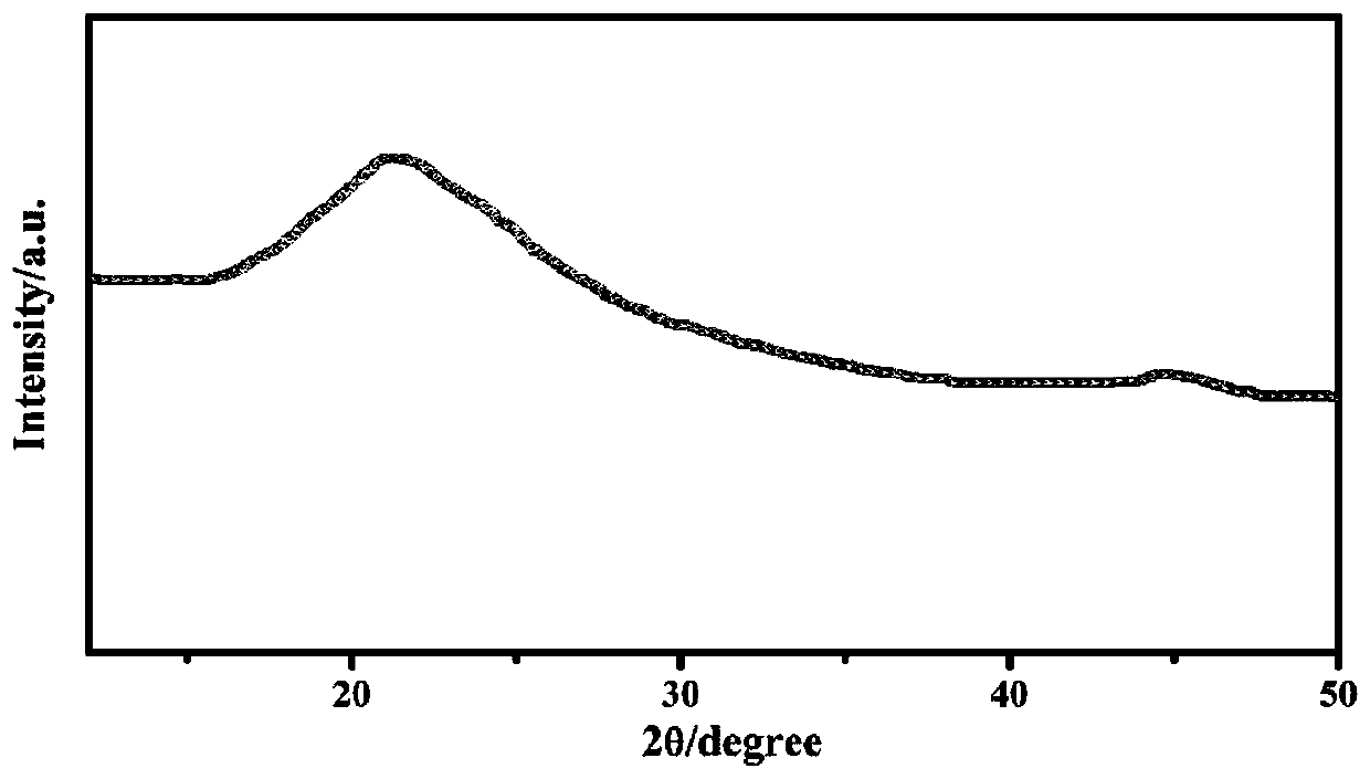
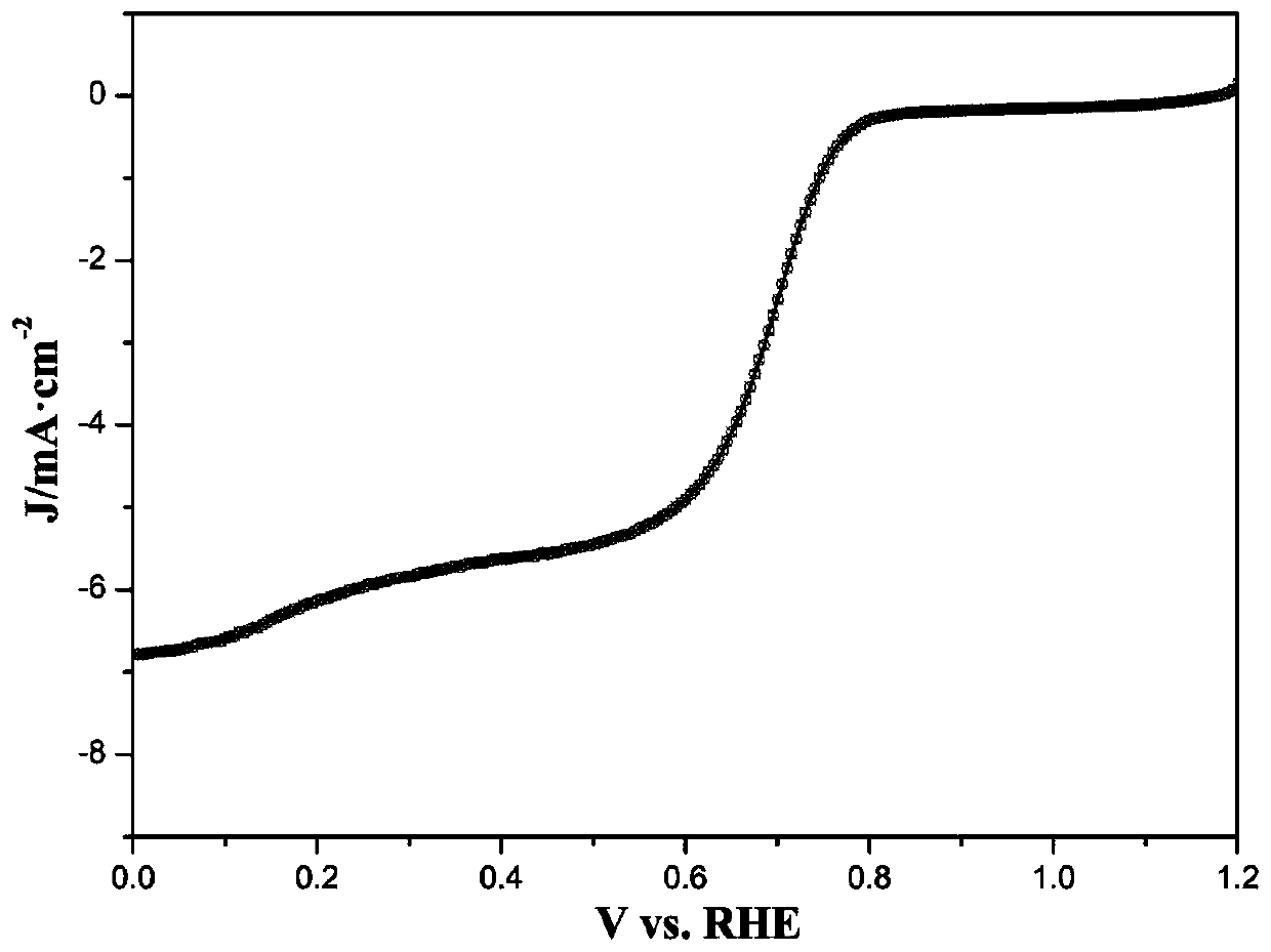
[0021] The oxygen reduction catalyst obtained in this embodiment is analyzed by XRD to obtain figure 1 ,Depend on figure 1 It can be seen that the main body of the material is a graphitized carbon material. The oxygen reduction catalyst obtained in this embodiment is subjected to linear voltammetry scanning, and the obtained figure 2 ,Depend on figure 2 I...
Embodiment 2
[0023] The preparation method of oxygen reduction catalyst is as follows:
[0024] Submerge 2g of carbon nanotubes in 200mL of nitric acid solution containing cysteine and boric acid (in this nitric acid solution containing cysteine and boric acid, the concentration of cysteine is 0.05mol / L, and the concentration of nitric acid is 0.1 mol / L), after standing and impregnating for 30 minutes, the carbon nanotubes were separated by filtration, vacuum dried at 40°C for 12 hours, then calcined at 850°C for 2 hours under a nitrogen atmosphere, and finally the obtained powder was ground by a high-speed ball mill at 2500rpm for 10 minutes to obtain oxygen reduction catalyst.
Embodiment 3
[0026] The preparation method of oxygen reduction catalyst is as follows:
[0027] Submerge 2g of carbon nanofibers in 200mL of a mixed aqueous solution of boric acid and phosphoric acid (in the mixed aqueous solution of boric acid and phosphoric acid, the concentration of boric acid is 0.1mol / L, and the concentration of phosphoric acid is 0.1mol / L), and after standing for 30min, filter and separate the carbon nanofibers. The nanofibers were vacuum-dried at 40°C for 12h, then calcined at 800°C for 2h under a nitrogen atmosphere, and finally the obtained powder was ground by a high-speed ball mill at 500rpm for 60min to obtain an oxygen reduction catalyst.
PUM
| Property | Measurement | Unit |
|---|---|---|
| specific surface area | aaaaa | aaaaa |
| specific surface area | aaaaa | aaaaa |
Abstract
Description
Claims
Application Information
 - R&D
- Intellectual Property
- Life Sciences
- Materials
- Tech Scout
- Unparalleled Data Quality
- Higher Quality Content
- 60% Fewer Hallucinations
Browse by: Latest US Patents, China's latest patents, Technical Efficacy Thesaurus, Application Domain, Technology Topic, Popular Technical Reports.
© 2025 PatSnap. All rights reserved.Legal|Privacy policy|Modern Slavery Act Transparency Statement|Sitemap|About US| Contact US: help@patsnap.com


