Liquid crystal display device
A liquid crystal display device, liquid crystal layer technology, applied in liquid crystal materials, instruments, chemical instruments and methods, etc., can solve the problems of white spots, uneven orientation, etc., and achieve the effect of preventing white spots and preventing decline
- Summary
- Abstract
- Description
- Claims
- Application Information
AI Technical Summary
Problems solved by technology
Method used
Image
Examples
preparation example Construction
[0333] Examples of thermoplastic resins used in the preparation of photocurable compositions include urethane resins, acrylic resins, polyamide resins, polyimide resins, styrene maleic resins, benzene Ethylene maleic anhydride resin, etc.
[0334]Examples of photocurable compounds include: 1,6-hexanediol diacrylate, ethylene glycol diacrylate, neopentyl glycol diacrylate, triethylene glycol diacrylate, bis(acryloxy Difunctional monomers such as ethoxy)bisphenol A, 3-methylpentanediol diacrylate, etc., trimethylolpropane triacrylate, pentaerythritol triacrylate, tris[2-(meth)propylene Acyloxyethyl] isocyanurate, dipentaerythritol hexaacrylate, dipentaerythritol pentaacrylate and other low molecular weight multifunctional monomers, polyester acrylate, polyurethane acrylate, polyether acrylate Such as polyfunctional monomers with larger molecular weight.
[0335] Examples of photopolymerization initiators include acetophenone, benzophenone, benzyl dimethyl ketal, benzoyl peroxi...
Embodiment 1~ Embodiment 5
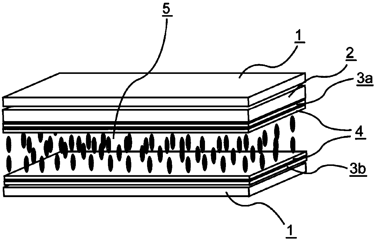
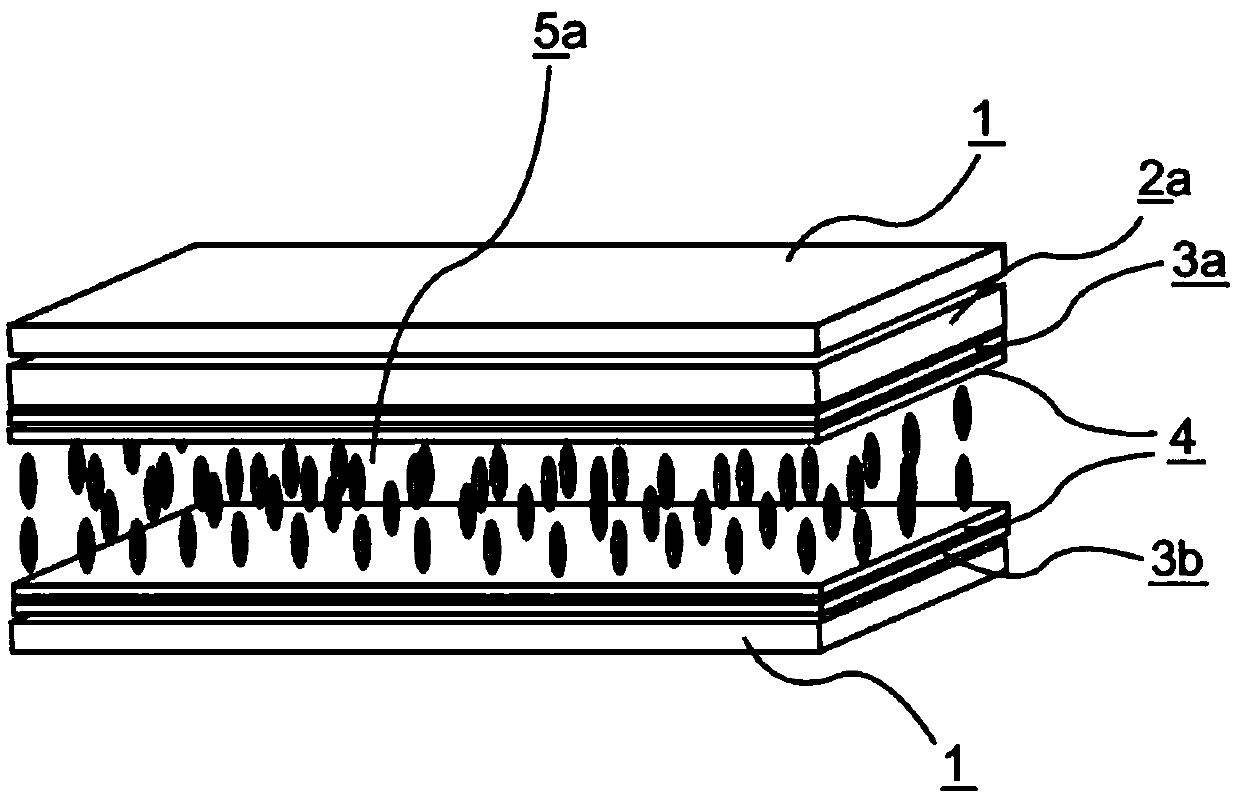
[0433] Electrode structures were formed on the first substrate and the second substrate, and a vertically oriented alignment film was formed on the respective opposite sides, followed by a weak rubbing treatment to make a VA unit, and the liquid crystal composition 1 shown in the following table was sandwiched held between the first substrate and the second substrate. Next, the liquid crystal display devices (d gap =3.5 μm, alignment film SE-5300). The VHR and ID of the obtained liquid crystal display device were measured. Moreover, the burn-in evaluation of the obtained liquid crystal display device was performed. The results are shown in the following tables.
[0434] [Table 12]
[0435]
Liquid crystal composition 1
T NI / ℃
74.3
Δn
0.122
Δε
-3.4
γ1 / mPa·s
127
3-Cy-Cy-2
18
3-Ph-Ph-1
6
3-Cy-Cy-Ph-1
6
3-Cy-Ph-Ph-2
6
V-Cy-Ph-Ph-3
6
3-Cy-Ph5-02
10
5-Cy-Ph5-02 ...
Embodiment 6~ Embodiment 20
[0441] In the same manner as in Example 1, liquid crystal display devices of Examples 6 to 20 were produced by interposing the liquid crystal compositions shown in the following table, and using color filters 1 to 5 shown in the tables. , and determine its VHR and ID. Moreover, the burn-in evaluation of the said liquid crystal display device was performed. The results are shown in the following tables.
[0442] [Table 14]
[0443]
[0444] [Table 15]
[0445]
[0446] [Table 16]
[0447]
[0448] [Table 17]
[0449]
[0450] The liquid crystal display devices of Examples 6 to 20 can realize high VHR and small ID. In addition, in the burn-in evaluation, there was no afterimage, or even if there was, it was extremely small and at an allowable level.
PUM
 Abstract
Description
Claims
Application Information
 - Generate Ideas
- Intellectual Property
- Life Sciences
- Materials
- Tech Scout
- Unparalleled Data Quality
- Higher Quality Content
- 60% Fewer Hallucinations
Browse by: Latest US Patents, China's latest patents, Technical Efficacy Thesaurus, Application Domain, Technology Topic, Popular Technical Reports.
© 2025 PatSnap. All rights reserved.Legal|Privacy policy|Modern Slavery Act Transparency Statement|Sitemap|About US| Contact US: help@patsnap.com


