
Locking pump for fast punch sliding-block oil cylinder locking

A technology for punch sliders and oil cylinders, which is applied in fluid pressure actuation devices, servo motors, and fluid pressure actuation system tests. It can solve the problems of high-speed punch cylinder pressure stability, no mandatory lubrication system, and slider and cylinder wear. Overspeed and other problems, to achieve the effect of ingenious design, good pressure holding performance and reduced wear of the cylinder

Pending Publication Date: 2019-04-02
HUAMAO MACHINERY ZHAOQING
View PDF0 Cites 0 Cited by
  • Summary
  • Abstract
  • Description
  • Claims
  • Application Information

AI Technical Summary

Problems solved by technology

[0005] The punch press with a punching speed of 1000 times / min in the market is called a high-speed punch. The existing high-speed punch generally does not have a mandatory lubrication system. The joints are only lubricated with butter, and the punch structure is a slider type, which is easy to damage. , In the prior art, the overload protection valve is generally used to protect the slider cylinder of the punch, but it is difficult to meet the pressure stability in the high-speed punch cylinder by simply using the overload protection valve, which will cause the slider cylinder to wear too fast and the accuracy will drop

Method used


Image

  • Locking pump for fast punch sliding-block oil cylinder locking
  • Locking pump for fast punch sliding-block oil cylinder locking
  • Locking pump for fast punch sliding-block oil cylinder locking

Examples


Embodiment

[0026] Embodiment: A locking pump used for fast punching slide block cylinder locking.

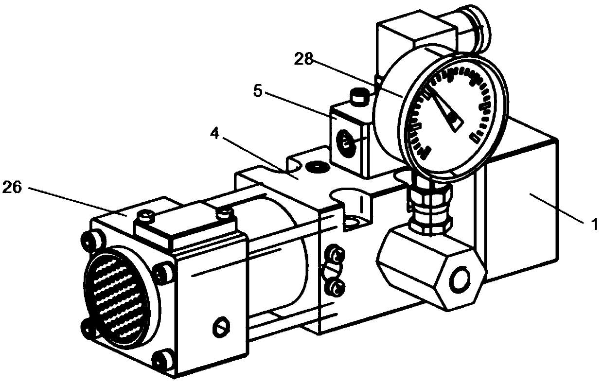
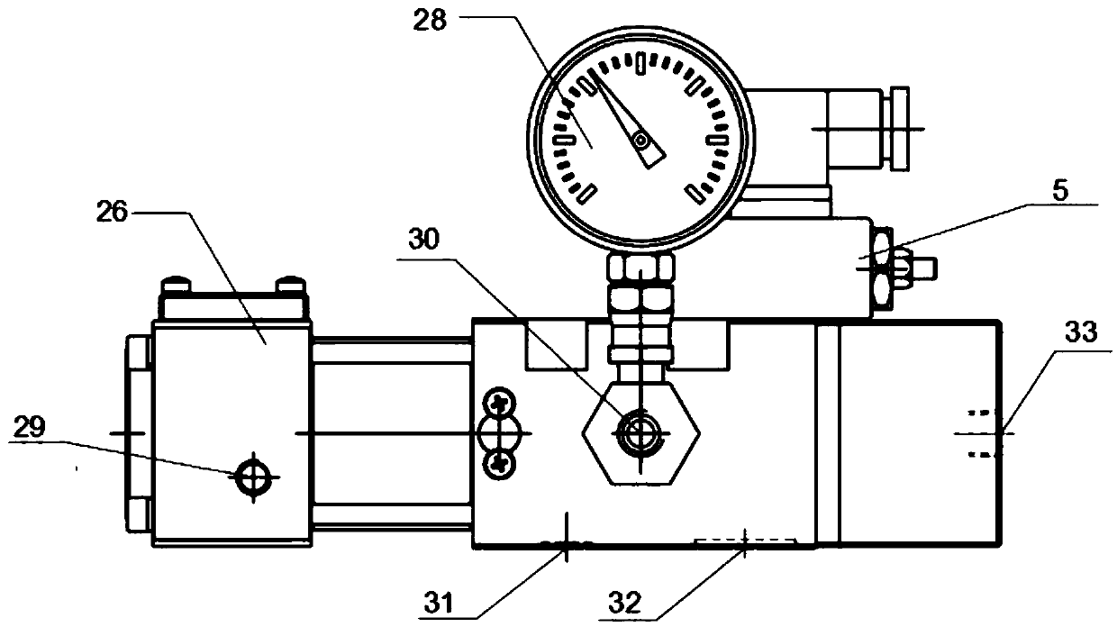
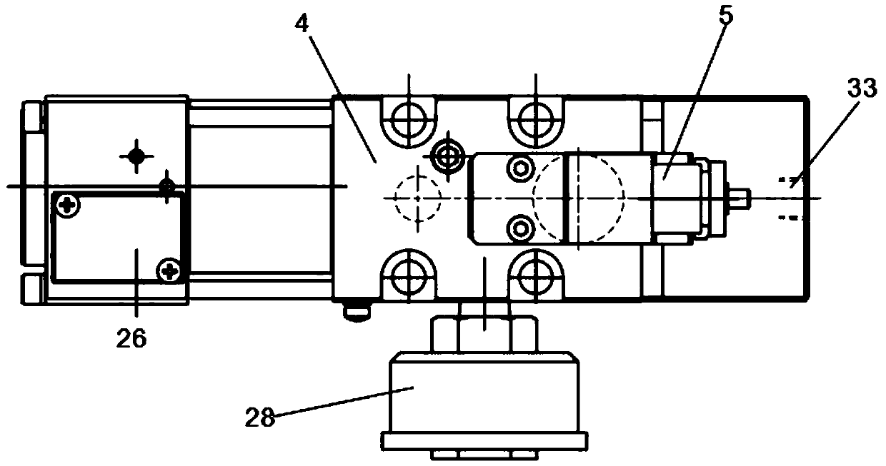
[0027] refer to Figure 1 to Figure 5As shown, a locking pump used for fast punching slide block cylinder locking includes: a locking pump housing 4; a first piston 2 installed on the left end side of the locking pump housing 4, and the first piston 2 The right side of the push rod 13 is fixedly installed, and the surface of the push rod 13 is sleeved with a return spring 14, the first piston 2 can drive the push rod 13 to move, and the reset of the first piston 2 is carried out by the return spring 14; Lock the cylinder head 1 on the left end side of the pump housing 4 and wrap the first piston 2, the middle part of the cylinder head 1 is provided with an unloading air supply port 33, and the unloading air supply port 33 communicates with the first piston 2; The unloading check valve 100 on the right side of the first piston 2 is provided with the oil return port 32 at the bottom of the ...


PUM


Abstract

The invention provides a locking pump for fast punch sliding-block oil cylinder locking. The locking pump comprises a locking pump shell, a first piston, an unloading one-way valve, an oil returning opening, a cylinder cover, an oil outlet, an oil suction and an air pump, wherein the first piston is arranged on the left end side of the locking pump shell, the unloading one-way valve is installed on the right side of the first piston, the oil returning opening is formed in the bottom of the locking pump shell, and the oil returning opening communicates with the unloading one-way valve; the cylinder cover is installed on the left end side of the locking pump shell and wraps the first piston, an unloading air supply opening is formed in the middle of the cylinder cover and communicates with the first piston, the oil outlet is formed in the middle of the front side of the locking pump shell, and a discharge one-way valve is arranged at the oil outlet; and the oil suction is formed in the bottom of the locking pump shell, a suction one-way valve is installed at the oil suction, and the air pump is installed on the right side of the locking pump shell. According to the locking pump for fast punch sliding-block oil cylinder locking, it can be guaranteed that the locking pump cannot be influenced by the change of oil pressure in a sliding block oil cylinder, and the stability of the oil cylinder pressure can be better maintained.

Description

technical field [0001] The invention relates to a locking pump, in particular to a locking pump used for fast punching press slider oil cylinder locking. Background technique [0002] A punch press is a stamping press. In national production, the stamping process has the advantages of saving materials and energy, high efficiency, low technical requirements for operators, and the ability to produce products that cannot be achieved by mechanical processing through various mold applications. It is used more and more widely. [0003] Stamping production is mainly for plates. Through the mold, blanking, punching, forming, deep drawing, trimming, fine blanking, shaping, riveting and extrusion parts can be made, which are widely used in various fields. For example, we use switch sockets, cups, cupboards, dishes, computer cases, and even missile aircraft. There are many accessories that can be produced by punching through molds. [0004] The design principle of the punching mach...

Claims


Application Information

Patent Timeline
IPC IPC(8): F15B11/08F15B13/02F15B15/26F15B19/00
CPCF15B11/08F15B13/02F15B15/26F15B19/00
Inventor 冯德祺余炳波郑志爽刘长海
Owner HUAMAO MACHINERY ZHAOQING
Learn More