
Anti-scratch clamping adjustable device in metal circular saw

A clamping device and circular sawing machine technology, applied in sawing machine devices, metal sawing equipment, metal processing equipment, etc., can solve problems such as pipe deformation, scratching cutting platform, damage to metal raw materials, etc., to improve service life, cutting The effect of high precision and guaranteed smoothness

Pending Publication Date: 2019-04-02
和和机械(张家港)有限公司
View PDF0 Cites 0 Cited by
  • Summary
  • Abstract
  • Description
  • Claims
  • Application Information

AI Technical Summary

Problems solved by technology

Since the metal raw material is conveyed against the cutting platform during the feeding process, it is inevitable that the metal raw material will collide with the cutting platform during the conveying process, which will scratch the cutting platform and damage the metal raw material
[0004] In addition, metal raw materials will inevitably have processing errors during the forming process. For metal raw materials with the same basic size given in the design, due to the existence of processing errors, the actual size of the final batches of metal raw materials cannot be guaranteed. It is exactly the same as the basic size given by the design, and there is no guarantee that the actual size between batches of metal raw materials is exactly the same
For multiple batches of metal raw materials of the same basic size, the clamping stroke of the clamping device is exactly the same, so when the actual size of the final formed metal raw material is slightly larger than the basic size, the clamping device will There will be over-clamping phenomenon in the process, the impact of over-clamping on bar-like metal raw materials is not great, but it has a great impact on tube-like metal raw materials, and the tube is easily deformed due to over-clamping
When the actual size of the final formed metal raw material is slightly smaller than the basic size, the clamping device cannot fully clamp the metal raw material

Method used


Image

  • Anti-scratch clamping adjustable device in metal circular saw
  • Anti-scratch clamping adjustable device in metal circular saw
  • Anti-scratch clamping adjustable device in metal circular saw

Examples


Embodiment 1

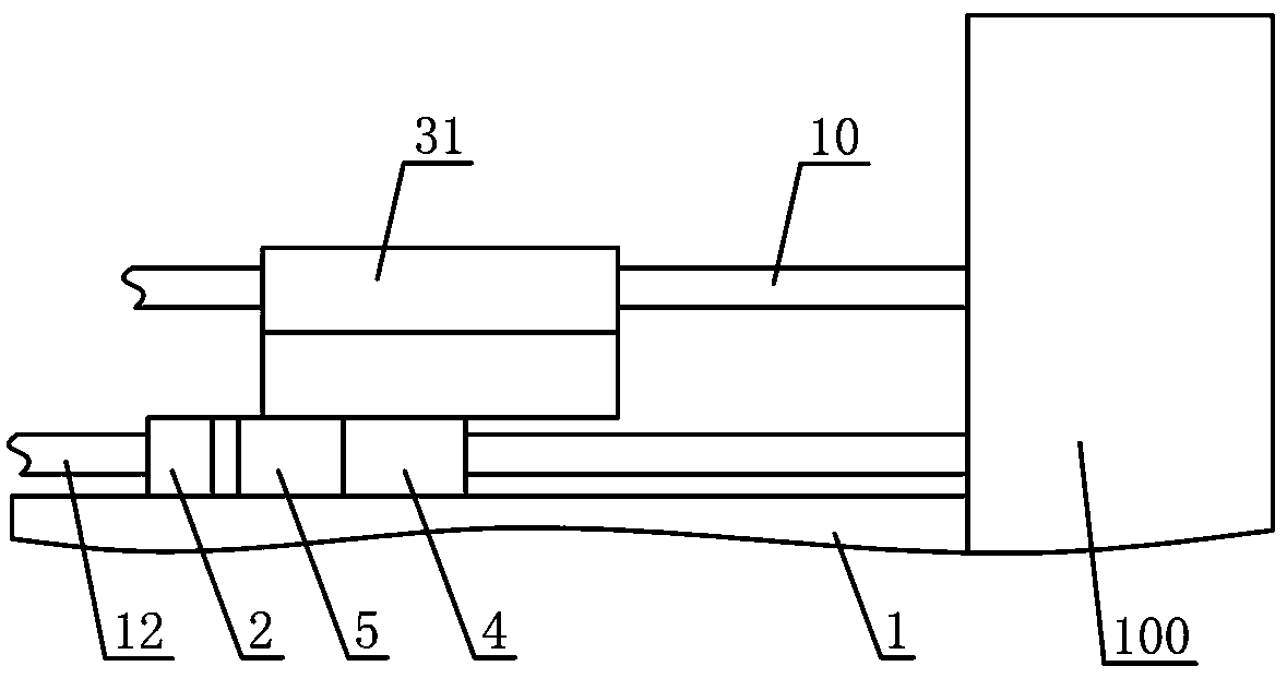
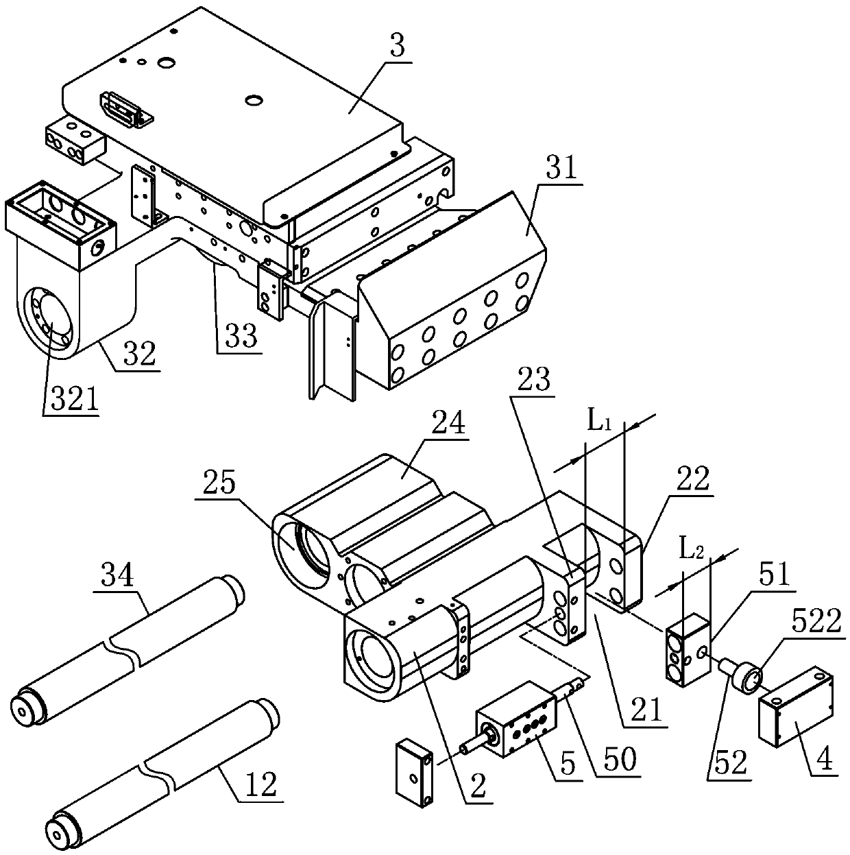
[0028] Such as figure 1 and Figure 4 As shown, the anti-scratch adjustable clamping device in the metal circular saw machine described in this embodiment includes: a frame 1, a cutting platform 11 is horizontally arranged on the frame 1, and the metal raw material 10 is clamped and fixed The clamping device 100 on the cutting platform 11. Such as Figure 6As shown, the clamping device 100 described in this embodiment includes: a horizontal clamp 6, and the structure of the horizontal clamp 6 is: a horizontal clamp seat 62 is provided on the frame 1, and the fixed clamp block 61 is fixedly arranged on the horizontal One side of the clamp seat 62 is provided with a first chute 64 on the horizontal clamp seat 62, and the rear part of the movable clamp block 63 is movably arranged in the first chute 64 of the horizontal clamp seat 62, between the fixed clamp block 61 and the movable clamp block. The top surface of the horizontal clamp seat 62 between the clamping blocks 63 for...

Embodiment 2

[0038] Such as Figure 4 and Figure 6 As shown, the difference between this embodiment and the first embodiment is that the clamping device 100 includes: a horizontal clamp 6 and a vertical clamp 7, and the structure of the horizontal clamp 6 is the same as that of the horizontal clamp in the first embodiment. The structure of 6 is consistent and will not be repeated here. Such as Figure 6 As shown, the structure of the vertical clamp 7 described in this embodiment is: a vertical clamp seat 71 is fixedly arranged on the frame 1, and the rear part of the vertical clamp block 72 is movably arranged on the vertical clamp seat 71. In the second chute 73, the vertical clamping block 72 is driven by the second double-rod cylinder 70 fixedly arranged on the top of the vertical clamp seat 71, and the upper side protruding rod 700 of the second double-rod cylinder 70 is connected with the second The hand wheels 702 are connected with each other, and a second threaded segment is pr...

Embodiment 3

[0046] Such as Figure 7 , Figure 8 and Figure 9 As shown, the difference between the present embodiment and the second embodiment is that a discharge pendulum 8 is hinged on the frame 1 located at the front side of the clamping device 100, and the discharge pendulum 8 can accept the load from the clamping device 100. Falling cutting material. On the frame 1 that is positioned at one side of the discharge pendulum 8, a material distribution cylinder 9 is fixedly arranged, and the extension rod 91 of the material distribution cylinder 9 is connected with the tail of the connecting rod 93 through a universal joint 92, and the material distribution cylinder 9, universal The connection between joint 92 and connecting rod 93 can be realized by threaded connection, such as Figure 9 As shown, the universal joint 92 is movably arranged in the movable hole at the tail end of the connecting rod 93 without falling out of the movable hole. The universal joint 92 is provided with a c...


PUM


Abstract

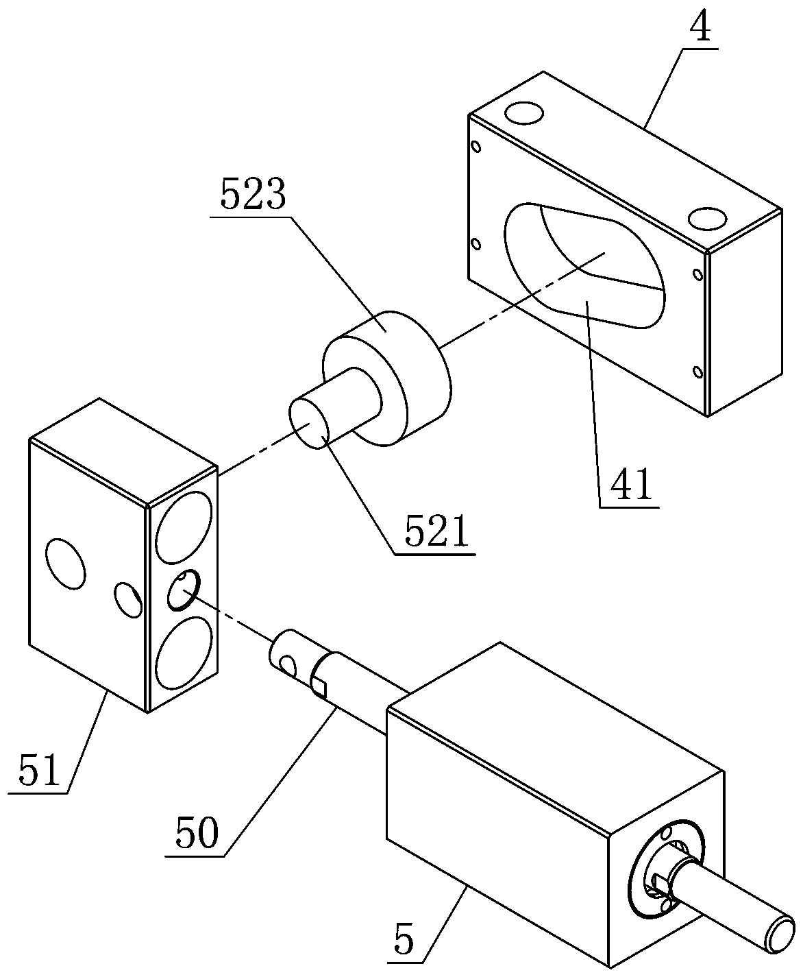
The invention discloses an anti-scratch clamping adjustable device in a metal circular saw. A cutting platform and a clamping device for clamping and fixing a metal raw material onto the cutting platform are horizontally arranged on a rack. Horizontal clamp forceps serve as the clamping device, a moving clamp block of the horizontal clamp forceps is driven by a first dual extension rod oil cylinder, a first extension rod of the first dual extension rod oil cylinder is connected with a first hand wheel, a first threaded segment is arranged on a second extension rod of the first dual extension rod oil cylinder, a first threaded hole is formed in the tail of the moving clamp block, and the second extension rod is screwed into the first threaded hole in the tail of the moving clamp block through the first threaded segment. An anti-scratch device is arranged at the position, located on the rear side of the clamping device, of the rack. By means of the device, the clamping stroke of the clamping device can be adjusted, and metal raw materials such as rods and pipes can be prevented from colliding with the cutting platform in the process of being fed into the cutting platform.

Description

technical field [0001] The invention relates to a metal circular saw machine, in particular to an adjustable anti-scratch clamping device in the metal circular saw machine. Background technique [0002] The metal circular saw machine is a kind of metal cutting equipment specially used for cutting and blanking metal raw materials such as bars and pipes. Among them, the feeding device and clamping device in the metal circular saw machine are the key components of the metal circular saw machine. It directly affects the cutting quality, cutting efficiency and service life of the saw blade. [0003] The current common metal circular saw machine is to send metal raw materials such as bars and pipes to the cutting platform through the feeding device, and then fix and clamp the metal raw materials on the cutting platform to the cutting platform through horizontal clamps. Since the metal raw material is conveyed against the cutting platform during the feeding process, it is inevitab...

Claims


Application Information

Patent Timeline
Patent Type & Authority Applications(China)
IPC IPC(8): B23D47/04
CPCB23D47/04B23D47/042
Inventor 黄俊杰
Owner 和和机械(张家港)有限公司
Learn More