Silicon wafer mounting machine

A technology for placement machines and silicon wafers, which is applied in the manufacture of conveyor objects, electrical components, semiconductor/solid-state devices, etc., can solve the problems of low work efficiency, low production efficiency, slow placement speed, etc. The effect of improving cooling efficiency

Pending Publication Date: 2019-03-29
金瑞泓科技(衢州)有限公司
View PDF7 Cites 2 Cited by
  • Summary
  • Abstract
  • Description
  • Claims
  • Application Information

AI Technical Summary

Problems solved by technology

[0002] Silicon wafer placement is an essential procedure in the silicon wafer processing process. At present, manual operations are mainly performed manually with the help of customized tooling fixtures. The work efficiency is low, the placement speed is slow, and the placement quality is unstable, which affects product quality and enterprise development.
The trays in and out of the box are manually placed, and the production efficiency is low

Method used


Image

  • Silicon wafer mounting machine
  • Silicon wafer mounting machine
  • Silicon wafer mounting machine

Examples


Embodiment

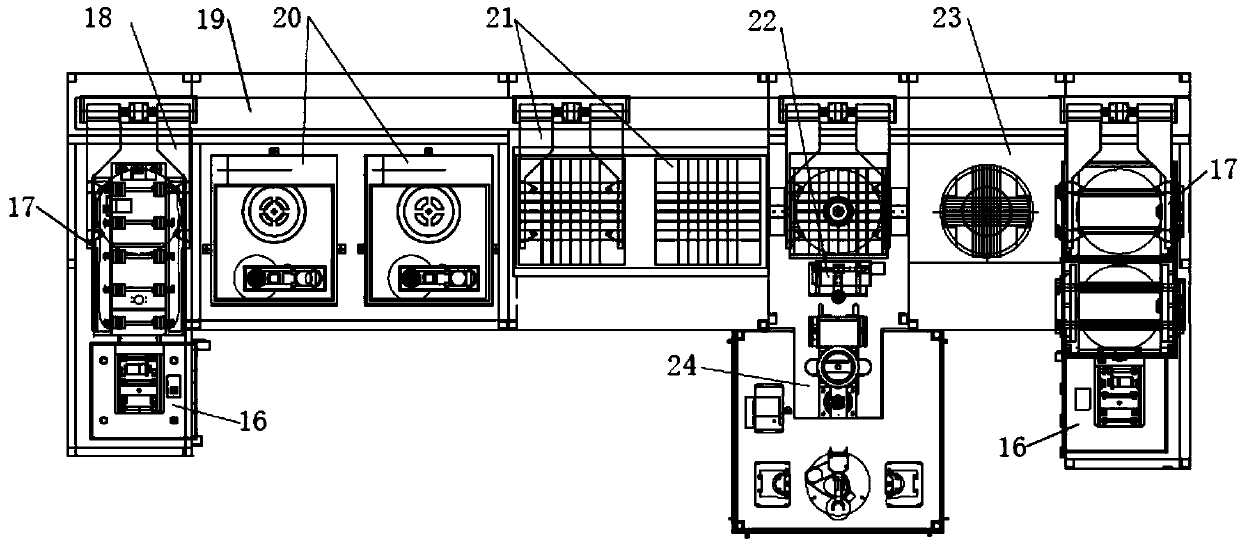
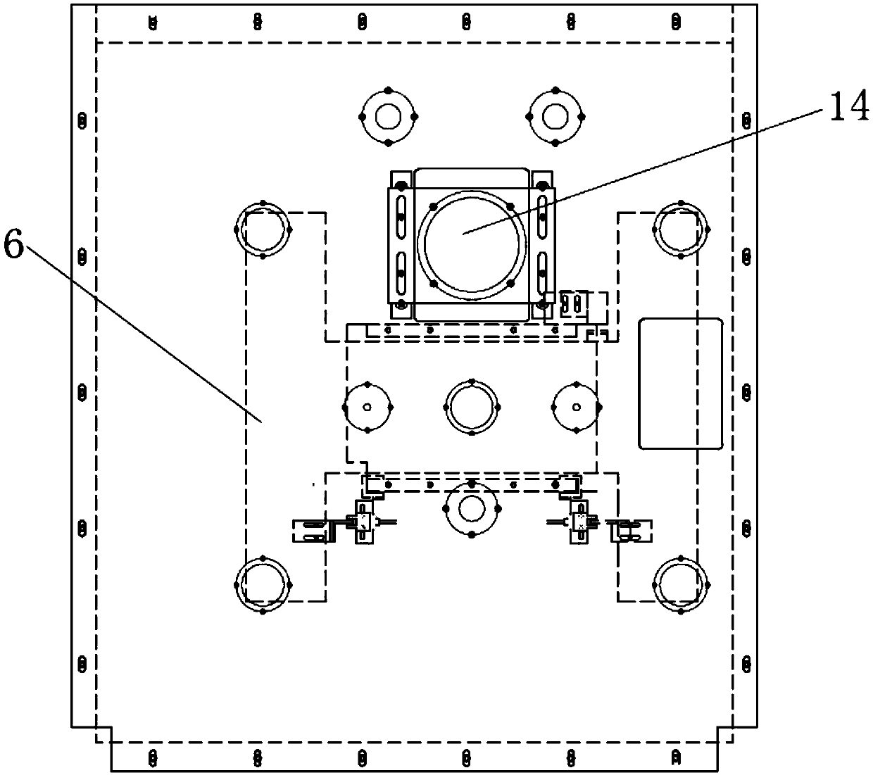
[0058] First push the trolley to the side of the tray inlet and outlet box lifting device 16 on the left side, and several tray inlet and outlet boxes on the cart are pushed into the top plate 2 of the lift frame together, and the left side and the front end of the top plate 2 of the lift frame pass through Baffle plate 15 surrounds, and first driving pulley is installed on the output shaft of the first servomotor 14, and first driving pulley links to each other with driven pulley 3 by belt, and driven pulley 3 drives screw mandrel 12 to rotate, and screw The rotation of the rod 12 drives the bottom plate 11 of the lifting frame and the top plate 2 of the lifting frame through the connecting sleeve 13 to descend. Put them on the first roller 30 one by one from bottom to top, then start the second servo motor 28, and the drive wheel 29 rotates to send the ceramic disc to the transmission mechanism 17. A grating ruler 8 is vertically installed on one side of the vertical plate 9...


PUM


Abstract

The invention relates to a silicon wafer mounting machine comprising tray in-out box lifting devices, a ceramic disc brushing device, a ceramic disc heating bench, a wax coating device, a flipping patch device, and a pressurizing cooling device. The tray in-out box lifting devices are arranged symmetrically left and right; transport mechanisms are arranged behind all tray in-out box lifting devices; the ceramic disc brushing device, the ceramic disc heating bench, the flipping patch device, and the pressurizing cooling device are installed successively between the rear parts of the two transport mechanisms from left to right; and the wax coating device is arranged in front of the flipping patch device. The silicon wafer mounting machine having the high automation degree is suitable for volume production.

Description

technical field [0001] The invention relates to the technical field of silicon chip placement machines, in particular to a silicon chip placement machine. Background technique [0002] Silicon wafer placement is an essential procedure in the silicon wafer processing process. At present, manual operations mainly rely on custom-made fixtures and fixtures with low work efficiency, slow placement speed, and unstable placement quality, which affects product quality and enterprise development. The trays in and out of the box are placed manually, and the production efficiency is low. Contents of the invention [0003] The technical problem to be solved by the present invention is to provide a silicon chip placement machine with a high degree of automation and suitable for mass production. [0004] The technical solution adopted by the present invention to solve the technical problem is to provide a silicon chip placement machine, including a lifting device for feeding and exitin...

Claims


Application Information

Patent Timeline
Patent Type & Authority Applications(China)
IPC IPC(8): H01L21/67H01L21/677H01L21/687
CPCH01L21/67103H01L21/67126H01L21/67703H01L21/68764
Inventor 徐继东胡晓光厉惠宏
Owner 金瑞泓科技(衢州)有限公司
Why Eureka
Try Eureka