
Novel micro-through plate and heating radiator and air conditioner tail end equipment provided with same

A through plate and plate technology, applied in the field of heat exchange, can solve the problems of uneven distribution of heat exchange medium, reduce the response speed of heat exchange, and increase the total weight of the radiator, so as to improve the quality and reliability, and improve the heat exchange effect. , light weight effect

Pending Publication Date: 2019-03-29
EXTEK ENERGY EQUIP ZHEJIANG
View PDF7 Cites 3 Cited by
  • Summary
  • Abstract
  • Description
  • Claims
  • Application Information

AI Technical Summary

Problems solved by technology

[0006] At present, radiator heat exchangers generally have one or more of the following problems. 1) Metal parts with thicker materials are used, which are heavy and costly
2) There are many welding processes or complex assembly processes, the manufacturability is not good, and the subsequent surface treatment affects the heat transfer effect
3) The distribution of the heat exchange medium is uneven, the diameter of some flow channels is large, there is temperature stratification, and the heat exchange efficiency is low
4) It is suitable for heat exchange at high water temperature of 60-90 degrees, but the heating effect is poor for low water temperature of 40-60 degrees
5) There is a large amount of water stored in the heat exchanger, which increases the total weight of the radiator, reduces the response speed of heat exchange, and causes heat loss

Method used


Image

  • Novel micro-through plate and heating radiator and air conditioner tail end equipment provided with same
  • Novel micro-through plate and heating radiator and air conditioner tail end equipment provided with same
  • Novel micro-through plate and heating radiator and air conditioner tail end equipment provided with same

Examples


Embodiment 1

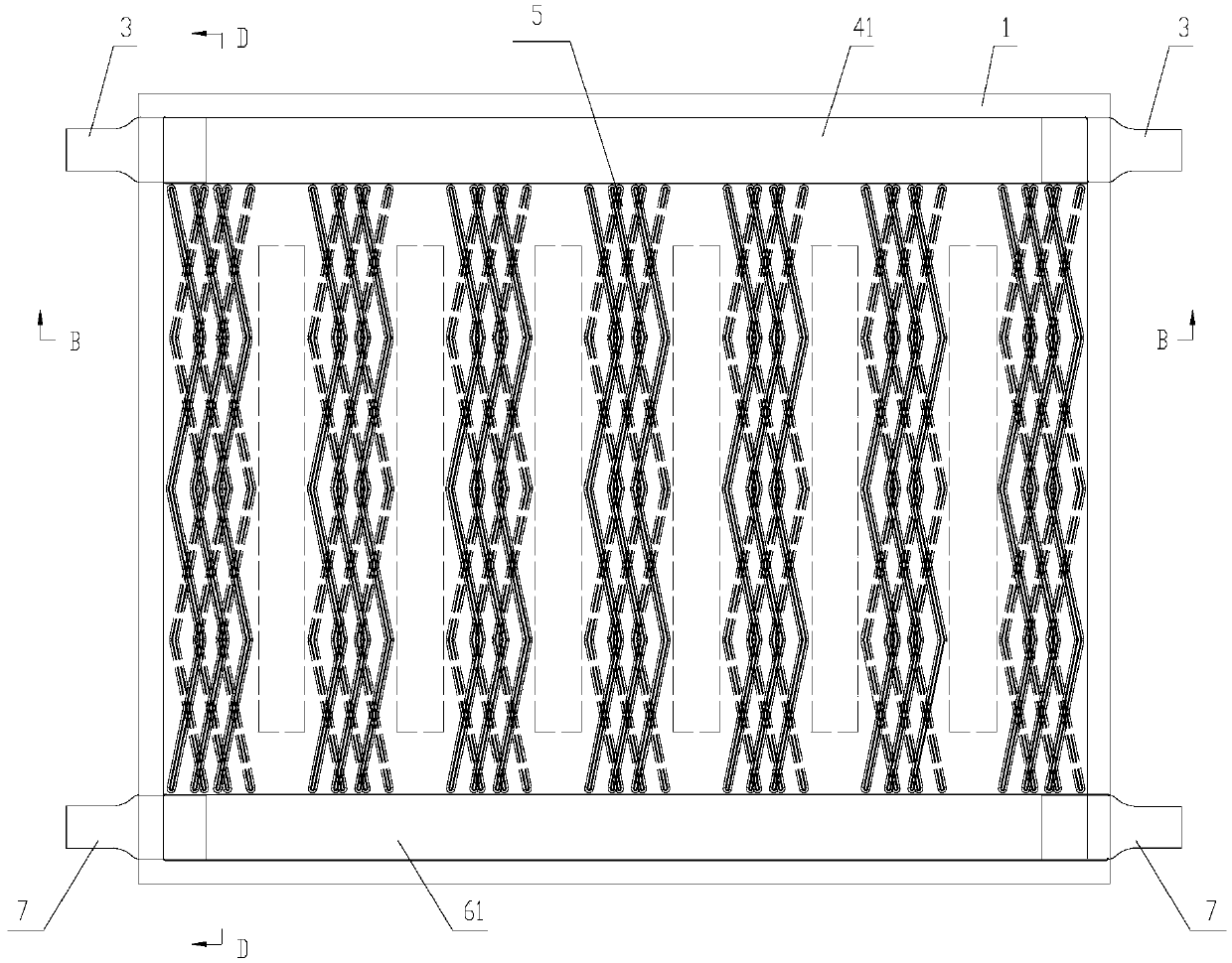
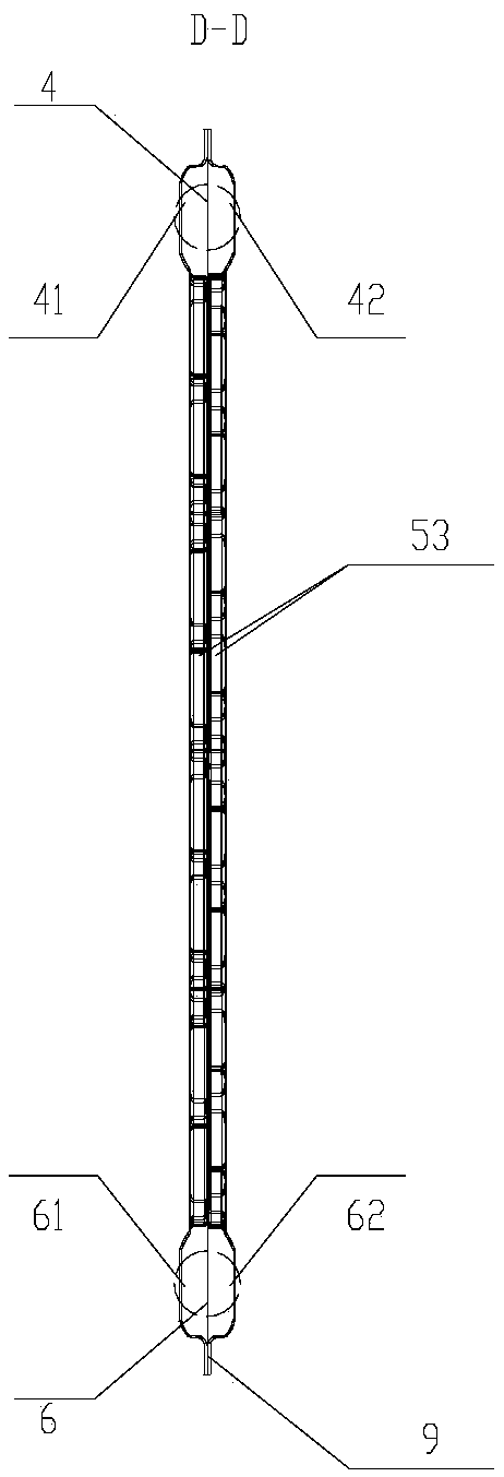
[0041] This embodiment relates to a micro-pass plate, such as Figure 1~5 shown. The micro-pass plate is compositely formed by two plates (the front plate 1 and the rear plate 2 are shown in the figure); specifically, the two plates are closely combined at the joint between the periphery and the middle protrusion. , the connection method mostly adopts the brazing method, and the raised joints 8 on the two plates are composited into a tight fixed point 81 by brazing. The tight fixing points 81 are evenly distributed on the inner side of the plates, and the tight fixing points 81 are mainly used for connection and fixing between two plates, which can ensure the bearing strength of the micro-through plate. In this embodiment, the plates can be processed first, and then the two plates can be combined into a micro-through plate by means of welding or the like. After compounding, except for the medium inlet and outlet, the micro-pass board is sealed all around, and the middle rais...

Embodiment approach

[0046] In the micro-through plate obtained based on the above scheme, at least two of the built-in micro heat exchange channels 5 intersect each other. The fluid medium in the tiny heat exchange channel 5 can generate turbulent flow and turbulent flow. Due to the turbulent flow and turbulent flow generated by the medium, the temperature stratification of the medium is disrupted, and the heat exchange effect is greatly improved. And based on the above principles, various implementation schemes are provided for the improvement of the micro-pass board, as follows:

[0047] (1), in the first scheme, the front plate and the rear plate are provided with corresponding raised joints and tiny medium flow grooves, and the raised joints are used as partitions between the tiny medium flow grooves, which can A dispersal effect is formed on the medium in the micro heat exchange channel 5, and the dispersed medium is distributed into two adjacent micro heat exchange channels, and so on. Dur...

Embodiment 2

[0055] This embodiment also relates to a micro-through plate. The difference between the micro-through plate and the micro-through plate mentioned in Example 1 is that in this solution, the heat-conducting component is externally connected to the heat exchange surface outside the plate. The heat conduction protrusion 21, the heat conduction protrusion 21 and the plates connected thereto form an outer channel for the second medium to pass through; the two ends of the outer channel respectively point to the distribution channel and the collection channel. In this solution, the heat conduction protrusion 21 is circumscribed on the outer heat exchange surface, while the heat conduction protrusion 21 in Embodiment 1 is obtained by integral punching of the plates. Therefore, in this embodiment, the entire tiny heat exchange channel is formed between the two outer heat exchange surfaces, and the heat conducting protrusions 21 can be connected to the plates by means of welding or the l...


PUM


Abstract

The invention relates to the field of heat exchange, and discloses a novel micro-flow plate. The micro-flow plate is formed by compounding two plate pieces and comprises an inner side medium flow channel and two outer side heat exchange surfaces; the inner side medium flow channel is composed of a distribution channel, a collecting channel and net-shaped crossed micro heat exchange channels; a first medium enters the micro-flow plate and is distributed by the distribution channel and then enters the net-shaped crossed micro heat exchange channels to be sufficiently turbulent, heat is exchangedbetween the two outer side heat exchange surfaces and the second medium on the outer side of the micro-through plate when flowing through the micro heat exchange channels; a heat conduction componentused for increasing the heat exchange area of the second medium is arranged on the outer side heat exchange surface of at least one of the two plate pieces. The micro heat exchange channels are uniformly distributed in the whole novel micro-through plates in a net-shaped staggered mode and ensures that the first medium fully utilizes the heat exchange surface; further, a heat conduction part is arranged on the outer side heat exchange surface of at least one plate piece, the heat exchange area of the second medium is increased through the arrangement of the heat conduction component, and themaximization of the heat exchange effect is facilitated.

Description

technical field [0001] The invention relates to the field of heat exchange, in particular to a novel micro-channel plate, radiators and air-conditioning terminal equipment provided with the micro-channel plate. Background technique [0002] A heat exchanger is a device that transfers part of the heat of a hot fluid to a cold fluid, also known as a heat exchanger. Heat exchangers play an important role in the field of home appliances, or in chemical, petroleum, power, food and many other industrial productions, and can be used as heaters, coolers, condensers, evaporators and reboilers. [0003] In my country, indoor heating devices in winter in the north have become a standard configuration for families, and indoor heating in winter in the south has also received increasing attention and gradually entered thousands of households. With the improvement of national environmental protection requirements, coal boilers that provide 60-90°C circulating hot water will be required to...

Claims


Application Information

Patent Timeline
Patent Type & Authority Applications(China)
IPC IPC(8): F28D1/03F28F3/04F24F13/30
CPCF24F13/30F28D1/0316F28F3/042
Inventor 方真健徐广安李和根
Owner EXTEK ENERGY EQUIP ZHEJIANG
Learn More