
Rear spoiler of automobile

A spoiler, automobile technology, applied in the direction of electric vehicles, body, vehicle parts, etc., can solve problems such as difficult to meet the demand, and achieve the effect of simple structure, good heat insulation and good stability

Inactive Publication Date: 2019-03-29
张荣国
View PDF0 Cites 0 Cited by
  • Summary
  • Abstract
  • Description
  • Claims
  • Application Information

AI Technical Summary

Problems solved by technology

[0004] The automatic lifting spoiler is one of the technologies commonly used in high-end cars at present, but it is only equipped on a small number of high-end cars at present, and there is no spoiler with automatic lifting function that can be installed in the later stage, which is difficult to meet the needs of the market. needs

Method used


Image

  • Rear spoiler of automobile
  • Rear spoiler of automobile
  • Rear spoiler of automobile

Examples


Embodiment 1

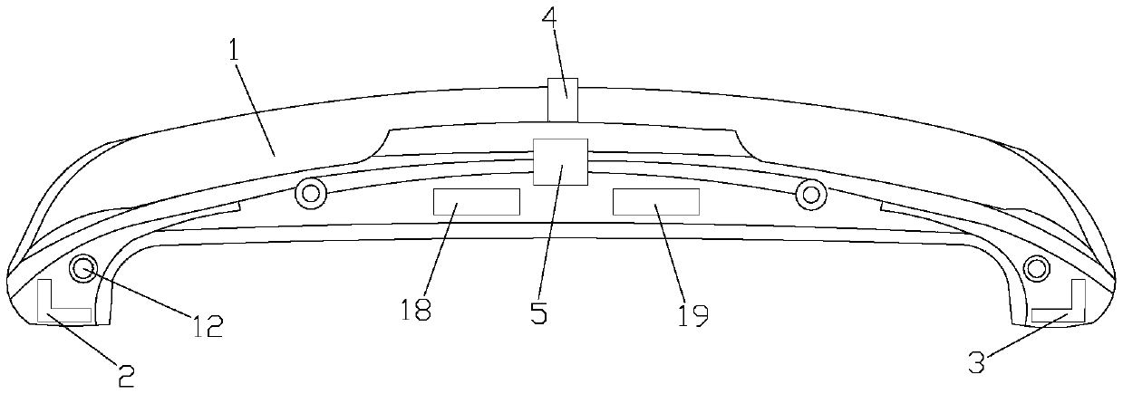
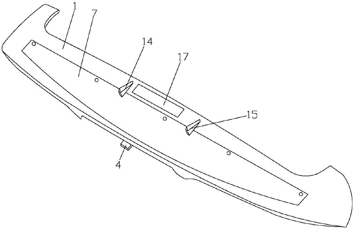
[0024] Such as Figure 1-4 As shown, a rear spoiler of an automobile comprises a spoiler body 1, the left and right ends of the spoiler body 1 are respectively provided with a first shock absorber 2 and a second shock absorber 3, the first Both the shock absorbing pad 2 and the second shock absorbing pad 3 are fixedly connected to the spoiler body 1, and the first shock absorbing pad 2 and the second shock absorbing pad 3 are all arranged in an L shape, and the back of the spoiler body 1 A speed sensor 4 and a control device 5 are provided, the detection end of the speed sensor 4 is set through the spoiler body 1, the detection end of the speed sensor 4 extends out of the spoiler body 1, and the spoiler body 1 A storage tank 6 is arranged on the front, and a thermally deformable spoiler 7 is arranged in the storage tank 6, and one edge of the thermally deformable spoiler 7 is bolted to the spoiler body 1, and the thermally deformable spoiler 7 includes Active layer 8, heat in...

Embodiment 2

[0027] Such as Figure 1-5As shown, a rear spoiler of an automobile comprises a spoiler body 1, the left and right ends of the spoiler body 1 are respectively provided with a first shock absorber 2 and a second shock absorber 3, the first Both the shock absorbing pad 2 and the second shock absorbing pad 3 are fixedly connected to the spoiler body 1, and the first shock absorbing pad 2 and the second shock absorbing pad 3 are all arranged in an L shape, and the back of the spoiler body 1 A speed sensor 4 and a control device 5 are provided, the detection end of the speed sensor 4 is set through the spoiler body 1, the detection end of the speed sensor 4 extends out of the spoiler body 1, and the spoiler body 1 A storage tank 6 is arranged on the front, and a thermally deformable spoiler 7 is arranged in the storage tank 6, and one edge of the thermally deformable spoiler 7 is bolted to the spoiler body 1, and the thermally deformable spoiler 7 includes Active layer 8, heat ins...


PUM


Abstract

The invention discloses a rear spoiler of an automobile. The rear spoiler of the automobile comprises a spoiler body, wherein the left end and right end of the spoiler body are provided with a first shock absorption pad and a second shock absorption pad respectively, the first shock absorption pad and the second shock absorption pad are both fixedly connected with the spoiler body, the first shockabsorption pad and the second shock absorption pad are both arranged in an L shape, the back face of the spoiler body is provided with a speed sensor and a control device, a detection end of the speed sensor penetrates through the spoiler body, the detection end of the speed sensor stretches out of the spoiler body, the front face of the spoiler body is provided with a storage groove, the storagegroove is internally provided with a thermal deformation turbulence body, one edge of the thermal deformation turbulence body is in bolted connection with the spoiler body, the thermal deformation turbulence body comprises an active layer, a thermal insulation silica gel layer, an electric heating network and a passive layer, the electric heating network is embedded into the thermal insulation silica gel layer, and the electric heating network closely fits the active layer. The rear spoiler of the automobile has an automatic rising and falling function.

Description

technical field [0001] The invention relates to an automobile rear spoiler. Background technique [0002] The spoiler of the car refers to the additional plate installed above the rear of the car, also known as the car tail. The function of the spoiler is mainly to reduce the lift of the rear of the vehicle. If the lift at the rear of the car is greater than that at the front, it will easily lead to excessive steering, reduced rear wheel grip, and poor high-speed stability. [0003] Like wind resistance, the lift force is proportional to the square of the vehicle speed, that is to say, the lift force at a speed of 120 kilometers per hour is 4 times that of a speed of 60 kilometers per hour, and 9 times that of a speed of 40 kilometers per hour. Therefore, cars with higher speeds, such as limousines and sports cars, are generally equipped with spoilers. [0004] The automatic lifting spoiler is one of the technologies commonly used in high-end cars at present, but it is onl...

Claims


Application Information

Patent Timeline
IPC IPC(8): B62D35/00H02J7/35
CPCB62D35/007H02J7/35Y02T10/82
Inventor 张荣国
Owner 张荣国
Learn More