Method and tooling for processing hydraulic cylinder with joint seat

A processing method and technology of hydraulic cylinders, applied in metal processing equipment, metal processing machinery parts, manufacturing tools, etc., can solve the problems of inability to ensure personnel safety, affecting cylinder processing efficiency, affecting production efficiency, etc., so as to reduce machining waste. The effect of reducing material cost and improving production efficiency

Active Publication Date: 2020-05-05
ZHENGZHOU COAL MINING MACHINERY GRP +1
View PDF6 Cites 0 Cited by
  • Summary
  • Abstract
  • Description
  • Claims
  • Application Information

AI Technical Summary

Problems solved by technology

Therefore, only the process after welding the joint seat of the upper cavity can realize the automatic processing of the automatic loading and unloading of the robot, which affects the processing efficiency of the cylinder from blanking to finished product
[0006] 3) Due to the uncertainty of human assembly size, it is necessary to measure the distance from the center of the upper chamber joint seat hole to the end face of the cylinder barrel one by one when carrying out the end face of the upper chamber joint seat of the flat cylinder, and then adjust the processing procedure, which seriously affects the production Efficiency, at the same time, manual assistance is required, and personnel safety cannot be guaranteed
[0007] 4) The distance tolerance from the center of the upper chamber joint seat hole to the end face of the cylinder barrel must be controlled within ±0.5mm. Due to the uncertainty of the size of the manual assembly, in order to ensure the distance from the center of the upper chamber joint seat hole to the end face of the cylinder barrel when the end face is flat, it is necessary to Increase the machining allowance of the end face process of the flat cylinder, usually 3-4mm allowance, resulting in waste of raw materials

Method used


Image

  • Method and tooling for processing hydraulic cylinder with joint seat
  • Method and tooling for processing hydraulic cylinder with joint seat
  • Method and tooling for processing hydraulic cylinder with joint seat

Examples


Embodiment Construction

[0038] The technical solutions of the present invention will be described in further detail below through specific implementation methods.

[0039] Such as Figure 1-Figure 5 As shown, a method for processing a hydraulic cylinder with an upper cavity joint seat is carried out according to the following steps:

[0040] 1) Cylinder blanking, use a sawing machine or a circular saw to cut and blank, and reserve a machining allowance of 4-6mm for the total length.

[0041] 2) Tailor-welding the joint seat 8 of the upper cavity, this step is carried out in two steps;

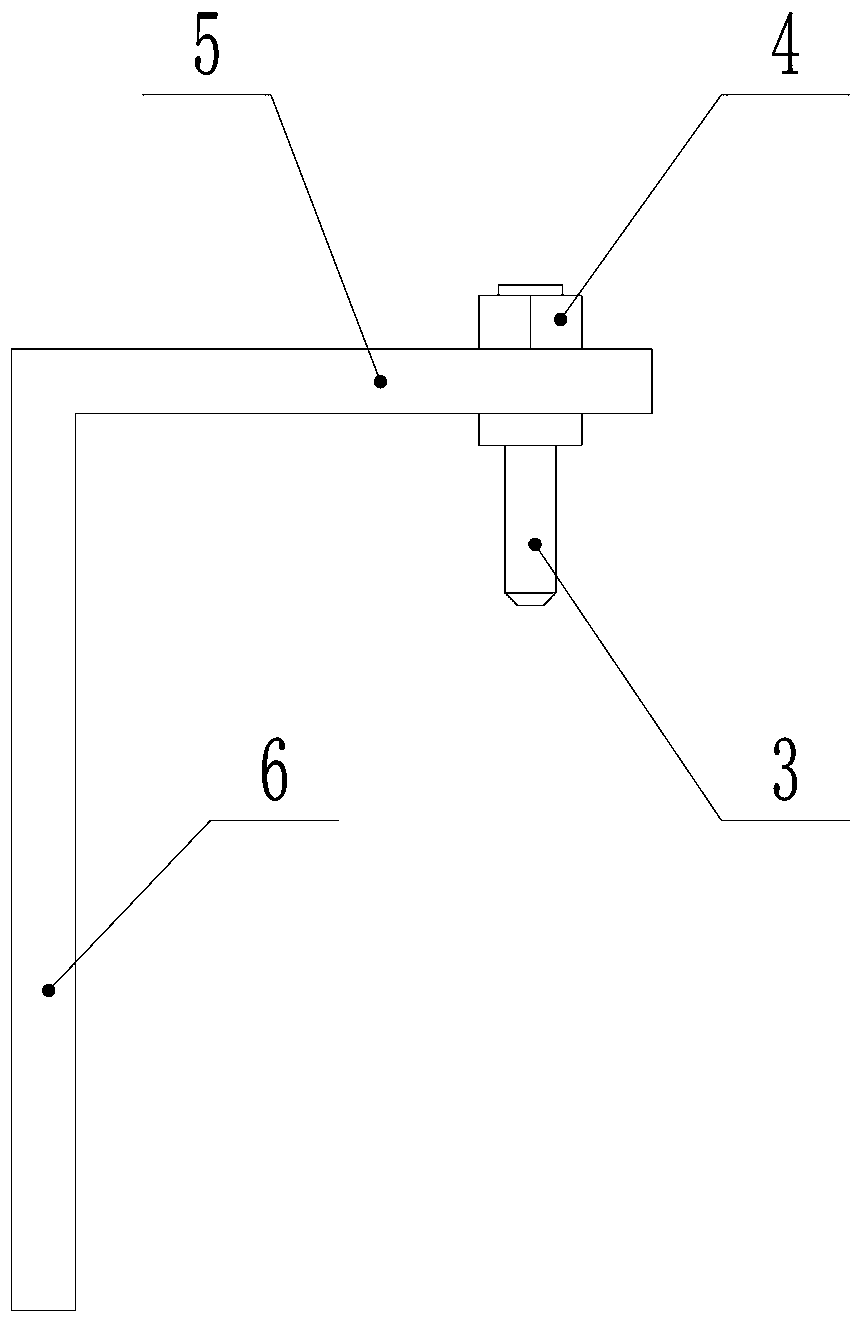
[0042] 2.1) Tooling adjustment before welding, the tooling includes L-shaped positioning plate 2, positioning pin 3 and lock nut 4, and the horizontal plane 5 of the L-shaped positioning plate is set and adjusted correspondingly to the locking nut 4 and positioning pin 3 The long slot 7, the positioning pin 3 can slide in the adjustment long slot 7 to adjust the specific position of the positioning pin 3; the vertic...


PUM


Abstract

The invention provides a machining method for a hydraulic cylinder barrel with an upper cavity joint seat. The machining method is performed according to the following steps of 1), cylinder barrel blanking; 2), an upper cavity joint seat butt-welding; 3), end facing and chamfering; 4), inner hole scraping and rolling; 5), turning of an inner spigot of the cylinder barrel; and 6) drilling, whereinin the case of the upper cavity joint seat butt-welding step, a tool is adopted for adjusting and positioning, and then butt-welding is performed. By adjusting the machining working procedures, the upper cavity joint seat which depends on manual butt-welding is arranged in front, most of the working procedures are placed back, so that the requirements of automatic machining are met, meanwhile, theinfluence of the butt-welding high heat on subsequent hole machining precision is reduced, the subsequent working procedures is used for machining by taking the upper cavity joint seat as the reference, the machining allowance in the blanking process can be properly reduced, and the cost is reduced.

Description

technical field [0001] The invention relates to a processing method and a processing tool for a hydraulic cylinder barrel with a processed upper chamber joint seat having a liquid passage hole. Background technique [0002] Hydraulic cylinders generally need to inject working fluid through the upper chamber or lower chamber of the piston to work, so ordinary hydraulic cylinders need to weld the upper chamber joint seat to connect the rubber hose, and the hydraulic cylinders with the upper chamber joint seat are all flat on the lathe After that, the head seat of the upper cavity is welded and assembled. Before welding the joint seat of the upper cavity, the assembly line is drawn manually, and then the center of the hole of the joint seat of the upper cavity is manually aligned with the center of the cross line. The processing technology of the cylinder with the joint seat of the upper cavity is: cylinder Blanking, flat head chamfering, tailor-welded upper chamber joint seat,...

Claims


Application Information

Patent Timeline
Patent Type & Authority Patents(China)
IPC IPC(8): B23P15/00B23Q3/18
CPCB23P15/00B23Q3/18
Inventor 孟贺超程相榜郑风波李瑞鹏赵旭刘超郭玉坤秦永峰孙满春
Owner ZHENGZHOU COAL MINING MACHINERY GRP
Why Eureka
Try Eureka