
Electromagnetic heating metal phase diagram experimental method and experimental test tube

An experimental method and metal phase technology, applied in the investigation phase/state change and other directions, can solve the problems of rapid sample cooling rate, scrapping, large phase diagram drawing errors, etc., to shorten the experimental time, increase the experimental efficiency, and accurately control the temperature. Effect

Inactive Publication Date: 2019-03-26
HANDAN COLLEGE
View PDF8 Cites 0 Cited by
  • Summary
  • Abstract
  • Description
  • Claims
  • Application Information

AI Technical Summary

Problems solved by technology

However, the fact is that for those who use this instrument for the first time, even if they are repeatedly reminded, their heating temperature will be much higher than the specified temperature, causing a large number of thermocouples to be burned out and scrapped every time;
[0007] 2. The two-component alloy phase diagram devices currently on the market are not only expensive, but also relatively complicated in design
When the mechanical parts are running mechanically, the noise is large, the wear is large, and the environment is polluted;
[0008] 3. The original equipment did not have a fast cooling program, which made the original plan that each group had to collect five sets of experimental data be compressed into two groups
[0010] 1. The thermal inertia of resistance heating is large, and it is difficult to control the temperature. It is easy to heat above the design temperature, causing the liquid paraffin to boil and the sample to deteriorate.
[0011] 2. If the heating is turned off in advance in order to control the temperature, it is easy to cause insufficient heating and uneven melting of the sample
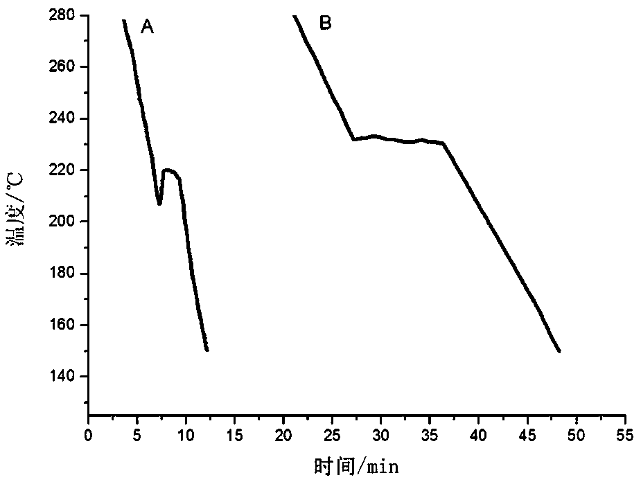
However, after the heating is stopped, a temperature difference is formed between the sample and room temperature. Due to the increased temperature difference, the cooling rate of the sample per unit time may be relatively fast, causing the temperature of the sample to reach the phase transition point (freezing point) to drop before the phase transition temperature occurs. up
Supercooling occurs on the step cooling curve, and the accurate phase transition temperature cannot be obtained, resulting in a large error in the drawing of the phase diagram

Method used


Image

  • Electromagnetic heating metal phase diagram experimental method and experimental test tube
  • Electromagnetic heating metal phase diagram experimental method and experimental test tube
  • Electromagnetic heating metal phase diagram experimental method and experimental test tube

Examples


Embodiment 1

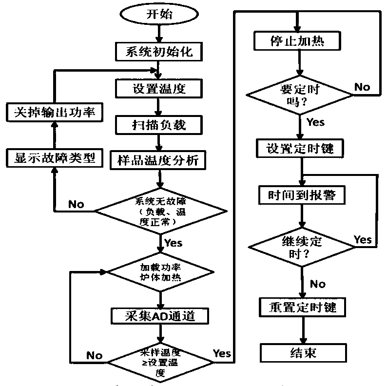
[0044] Such as figure 1 It is shown that the system initializes at the beginning of this method and sets the sample heating temperature. Since there is no residual heat in electromagnetic heating technology, the temperature is generally set at a position 40-50°C higher than the melting point of the sample in this experiment. The single-chip microcomputer scans whether there is a load in the heating furnace and the effectiveness of the load according to the magnitude of the input and output current and the direct relationship between the two, so as to avoid damage to electronic components due to excessive current.

[0045] The sample temperature detected by the thermocouple is transmitted to the single-chip control system by the AD acquisition card. After the system detects that all input signals are normal, the self-check passes. If a fault occurs, the system stops outputting current and displays the fault type on the instrument panel display to help users check the instrument’s p...

Embodiment 2

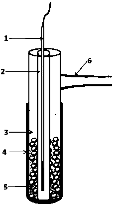
[0048] Such as figure 2 An electromagnetically heated metal phase diagram experimental test tube includes a test tube, an inner test tube and a cast iron sleeve. The inner test tube is set in the test tube, and the test tube is provided with liquid paraffin. A metal sample is impregnated in the paraffin, the test tube is provided with a test tube inlet, and the inner tube of the test tube is provided with a temperature sensor.

[0049] Electromagnetic heating requires that the heated body must be a magnetic material. On the outside of the original metal phase diagram measurement glass test tube, the cast iron sleeve is nested. Because cast iron has better magnetic permeability, higher electrical resistance and high thermal conductivity, it can meet the requirements of electromagnetic heating receivers. When the improved test tube is put into the heating furnace, under the action of electromagnetic heating, the cast iron sleeve begins to heat, and then heats the sample in the tub...


PUM


Abstract

The invention relates to the technical field of heaters and specifically relates to an electromagnetic heating metal phase diagram experimental method and an experimental test tube. According to the experimental method disclosed by the invention, a system is initiated, a sample heating temperature is set, whether a loader exists in a heating furnace is scanned by a single chip microcomputer, effectiveness of the loader is scanned by the single chip microcomputer, and an electronic component is prevented from being damaged by too large current. After all input signals are detected by the systemand are all normal, self check passes. After the self check passes, an instrument begins to formally output current to heat a sample, the temperature of the sample is collected by the system in realtime and is compared with the set temperature; when the temperature of the sample is lower than the set temperature, the system continues heating the sample; when the temperature of the sample is higher than the set temperature, the system stops heating the sample and begins cooling; meanwhile, a timing function is started, count down time is set according to need, and an operator is reminded to write down the temperature in the corresponding interval until an experiment is finished. According to the experimental method disclosed by the invention, the relationship between temperature and timein a cooling process is measured, an inflection point and a cooling platform are drawn in the cooling process, and an accurate phase change temperature can be obtained.

Description

Technical field [0001] The invention relates to the technical field of heaters, in particular to an electromagnetic heating metal phase diagram experimental method and an experimental test tube. Background technique [0002] Thermal analysis is an analytical method in physical chemistry and one of the basic methods for drawing phase diagrams. It is based on the principle that the phase change of a substance is accompanied by a thermal effect. When the melt (metal, alloy or compound) is uniformly cooled, if no phase change occurs, the temperature of the system will drop uniformly. If a phase change occurs during the cooling process, the temperature change of the system becomes unbalanced, and a horizontal line or turning point appears on the cooling (or heating) curve (temperature-time relationship curve). In physical chemistry experiments, the phase diagram of the binary alloy system is often obtained by making the step cooling curve of the sample. The system is gradually coole...

Claims


Application Information

Patent Timeline
Patent Type & Authority Applications(China)
IPC IPC(8): G01N25/04
CPCG01N25/04
Inventor 胡俊平谢鹏涛耿付江
Owner HANDAN COLLEGE
Learn More