
Non-dilution blower device for high-efficiency water heater

A water heater and blower technology, which is applied to the components of the pumping device for elastic fluid, the pump device, the fluid heater, etc., can solve the problems of nut loosening, loud motor noise, and foreign objects can enter the pipeline, etc., and achieve convenient installation. and disassembly, good sound insulation, good protection effect

Inactive Publication Date: 2019-03-26
ZHONGSHAN CITY HENG YUE ELECTRICAL APPLIANCE CO LTD
View PDF15 Cites 0 Cited by
  • Summary
  • Abstract
  • Description
  • Claims
  • Application Information

AI Technical Summary

Problems solved by technology

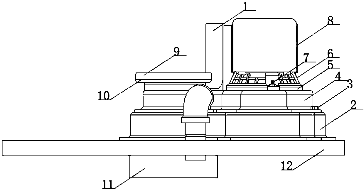
[0004] The purpose of the present invention is to provide a non-dilution blower device for high-efficiency water heaters, to solve the above-mentioned background technology when the non-dilution blower is running, it is necessary to connect the blower port with the water heater exhaust pipe to achieve communication. Purpose, but in actual use, the interior of the exhaust pipe of the water heater is connected to the atmospheric environment, so foreign matter can enter the interior of the water heater through the pipe, thereby affecting the normal use of the water heater, and when the blower is running, the motor produces a loud sound, and this The continuation of this sound will cause the user to experience hearing fatigue, which is not conducive to the comfort of the user. When the impeller connected to the motor is driven and rotated by the transmission rod, there is a nut to fix it, and the motor will vibrate when it is in use, and If the nut port is facing down, it is easy to loosen the nut, which will cause the blower to fail.

Method used


Image

  • Non-dilution blower device for high-efficiency water heater
  • Non-dilution blower device for high-efficiency water heater
  • Non-dilution blower device for high-efficiency water heater

Examples


Embodiment Construction

[0029] The following will clearly and completely describe the technical solutions in the embodiments of the present invention with reference to the accompanying drawings in the embodiments of the present invention. Obviously, the described embodiments are only some, not all, embodiments of the present invention. Based on the embodiments of the present invention, all other embodiments obtained by persons of ordinary skill in the art without making creative efforts belong to the protection scope of the present invention.

[0030] see Figure 1-7 , the present invention provides a technical solution:

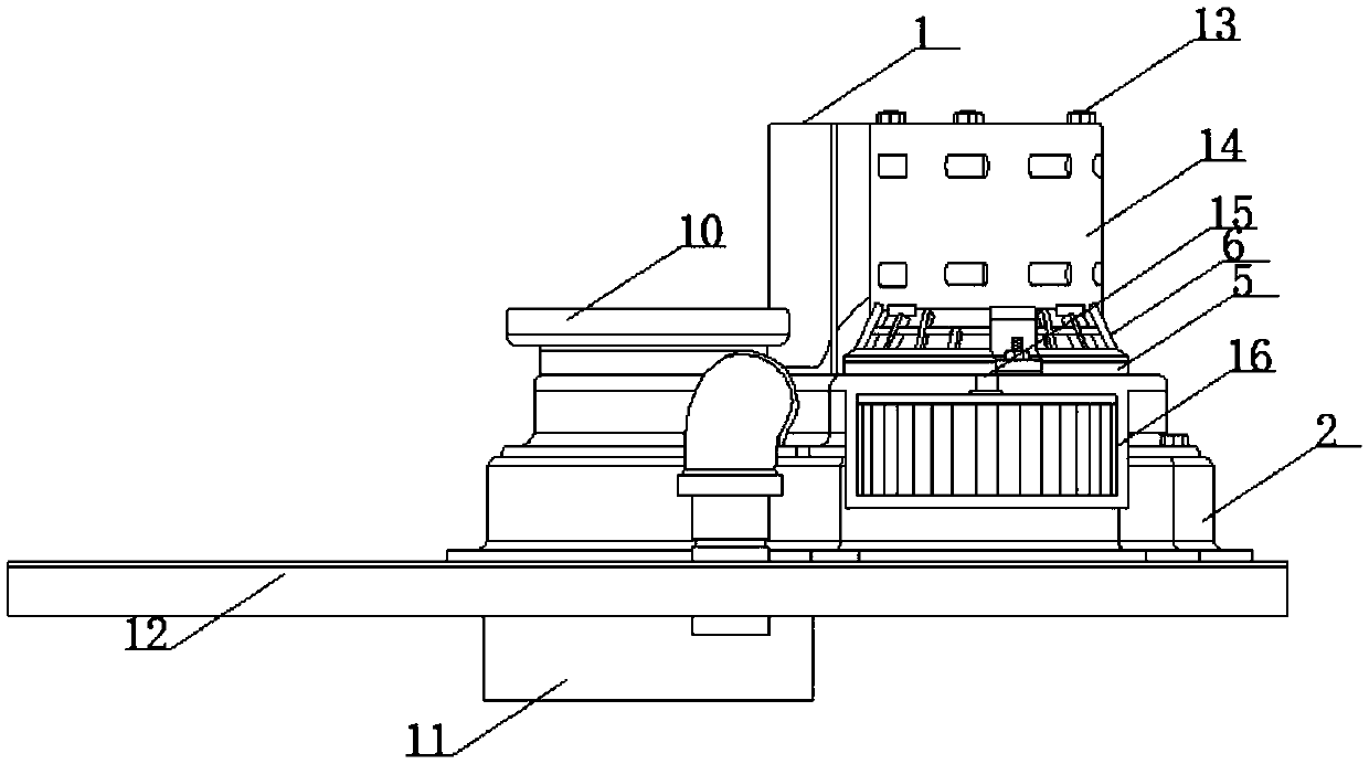
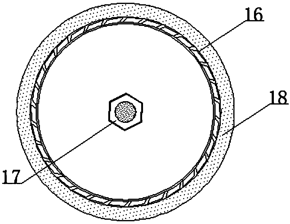
[0031] A non-dilution blower device for a high-efficiency water heater, comprising a water heater top 12 and a flue pipe 10, the top of the water heater top 12 is provided with a flue pipe 10, and the bottom end of the flue pipe 10 is fixedly connected to the water heater machine by welding The top of the top 12, and the bottom end of the flue pipe 10 is perpendicular to the top 1...


PUM


Abstract

The invention discloses a non-dilution blower device for a high-efficiency water heater. The non-dilution blower device comprises a water heater roof and a flue pipe, the top end of the water heater roof is provided with the flue pipe, the bottom end of the flue pipe is fixedly connected to the top end of the water heater roof through welding, the bottom end of the flue pipe is perpendicular to the water heater roof to be in a circular through shape, a water heater exhaust pipe is arranged below the flue pipe, the top end of the water heater exhaust pipe is fixedly connected to the circular through shaped bottom end of the water heater roof through welding, an air plate device is arranged at the top end inside the flue pipe, the air plate device is movably connected to the interior of theflue pipe through welding, the flue pipe is connected with the air plate device in a sleeve manner, and a quartz acoustic panel and the surface of a motor are not connected, the quartz acoustic panelis fixed to the outer surface of the motor through self gravity, the quartz acoustic panel can be conveniently installed and disassembled, and the non-dilution blower device is more humanized and relatively practical.

Description

technical field [0001] The invention belongs to the related technical field of blower devices, and in particular relates to a non-dilution blower device for high-efficiency water heaters. Background technique [0002] In the basic construction of a water heater, a fuel such as gas is burned in the heater's combustion chamber to heat water that passes through the water heater, usually through a series of coils in the water heater. Combustion of the fuel in the combustion chamber produces hot combustion exhaust gases which pass through a series of coils and heat the water passing through the coils, the combustion exhaust gases then leave the water heater through the exhaust of the water heater and then through a flue pipe which transfers the gases to Export the building containing the water heater. [0003] The existing non-dilution blower device technology has the following problems: when the non-dilution blower is running, it is necessary to connect the blower port with the...

Claims


Application Information

Patent Timeline
Patent Type & Authority Applications(China)
IPC IPC(8): F24H9/00F04D29/26F04D25/08F04D29/60
CPCF04D25/08F04D29/263F04D29/60F24H9/0005
Inventor 程洪向熹
Owner ZHONGSHAN CITY HENG YUE ELECTRICAL APPLIANCE CO LTD
Learn More