
Resistance adjusting mechanism of magnetic control bodybuilding /competition vehicle

A resistance adjustment, racing car technology, applied in the field of fitness equipment, can solve the problems of brake pad wear, distance difference, and affecting the smoothness of the inertial wheel rotation, and achieve the effect of ensuring magnetic resistance and smoothness

Inactive Publication Date: 2019-03-26
XIAMEN AOLRO TECH +1
View PDF0 Cites 2 Cited by
  • Summary
  • Abstract
  • Description
  • Claims
  • Application Information

AI Technical Summary

Problems solved by technology

In the inertia wheel mechanism of the fitness / racing car in the prior art, a resistance adjustment mechanism generally needs to be provided to adjust the resistance of the inertia wheel. The traditional resistance adjustment mechanism uses the contact between the brake pad and the inertia wheel to realize resistance adjustment. The sheet is prone to wear and tear, and the purpose of precisely adjusting the resistance cannot be achieved
The other in the prior art is to adjust the resistance by means of magnetic control. In this magnetic control mechanism, one end of the magnetic plate assembly is installed on the vehicle frame, and the other end is connected with a pull wire, and the other end of the magnetic plate assembly is pulled by the pull wire. The adjustment of the resistance is realized by adjusting the distance between the other end of the magnetic plate assembly and the inertia wheel. Since one end of the magnetic plate assembly is fixed, the distance between the magnetic plate assembly and the rim of the inertia wheel is different, resulting in The reluctance of the inertia wheel is uneven, which affects the smoothness of the inertia wheel rotation

Method used


Image

  • Resistance adjusting mechanism of magnetic control bodybuilding /competition vehicle
  • Resistance adjusting mechanism of magnetic control bodybuilding /competition vehicle
  • Resistance adjusting mechanism of magnetic control bodybuilding /competition vehicle

Examples


Embodiment 1

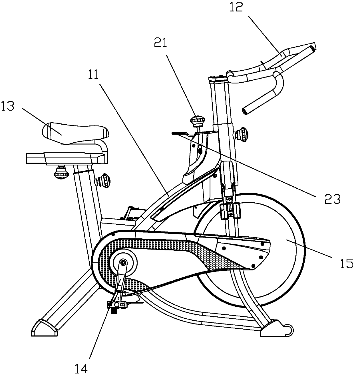
[0030] see figure 1 Described, a kind of magnetically controlled fitness / competition car of the present invention comprises vehicle frame 11, armrest 12, seat cushion 13, pedal wheel mechanism 14 and inertial wheel 15, and armrest 12 and seat cushion 13 are contained on the vehicle frame 11 respectively , pedal wheel mechanism 14 and inertia wheel 15 are also contained respectively on the vehicle frame 11 and are in the position of matching, when pedal wheel mechanism 14 moves, can drive inertia wheel 15 to rotate.

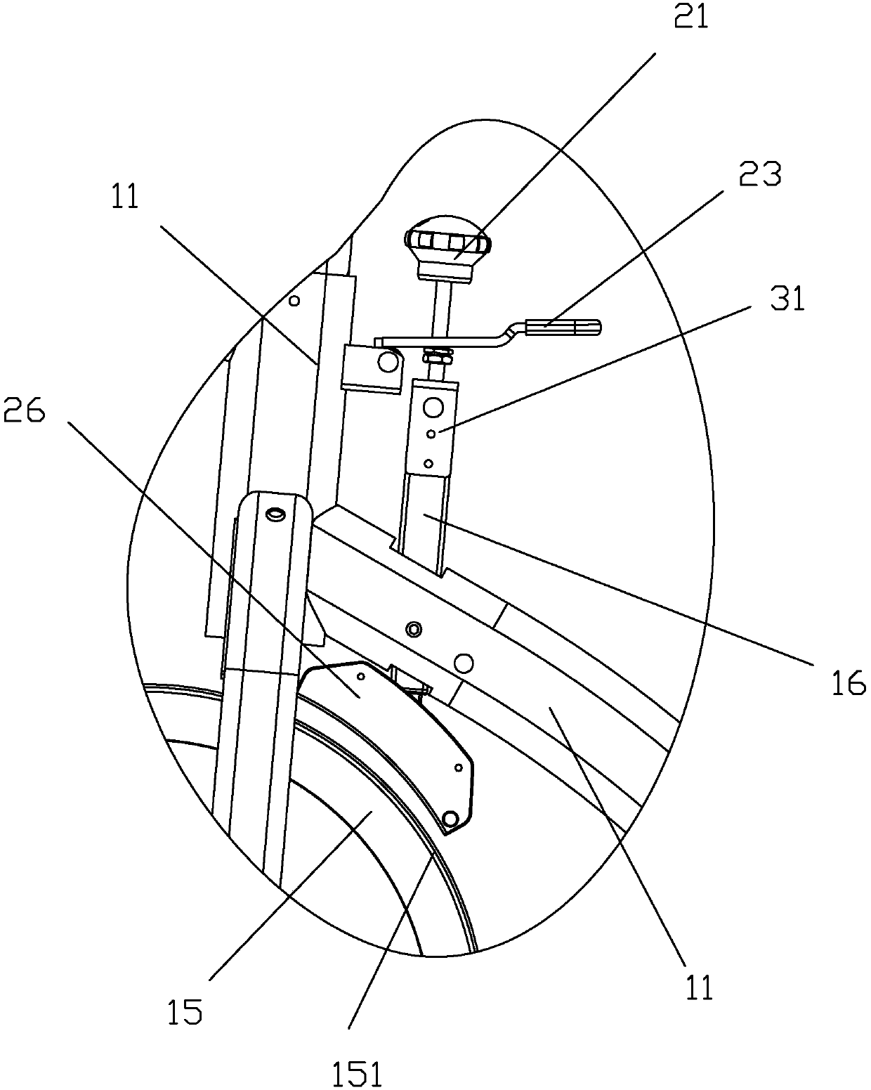
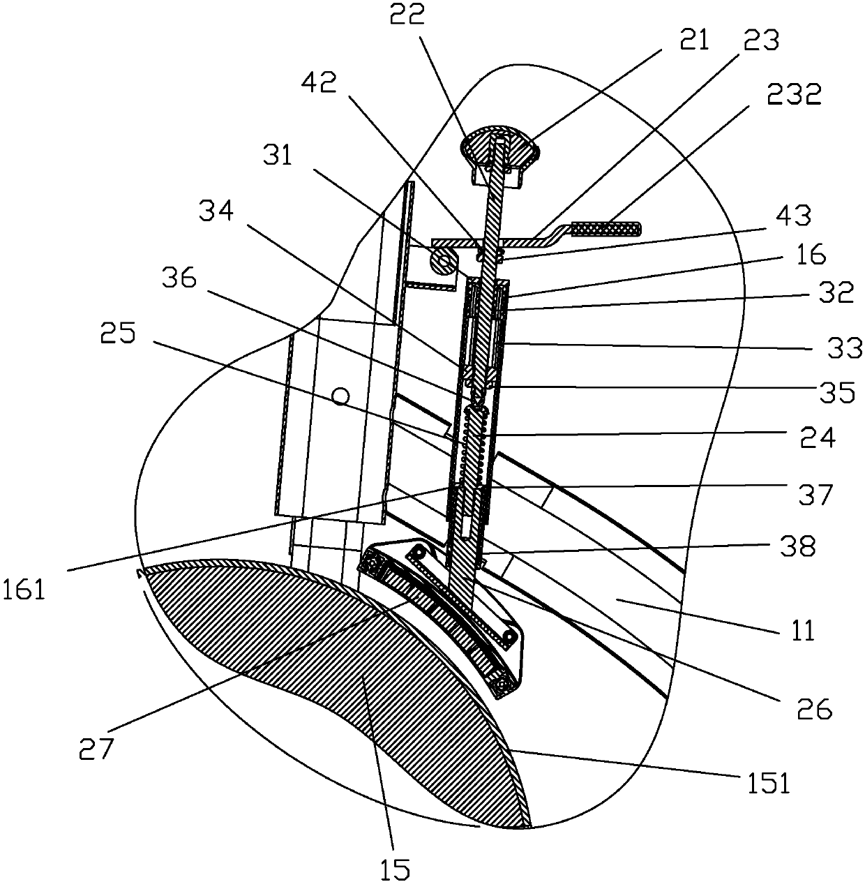
[0031] see Figure 2 to Figure 4 As mentioned above, the resistance adjustment mechanism of a magnetically controlled fitness / racing car of the present invention includes a casing 16, a brake screw 22, a stopper 33, a first nut 34, a bolt 24, a first compression spring 25, and a magnetic plate to fix the frame 26 and magnet block 27; the sleeve 16 is installed at the vehicle frame 11 corresponding to the position of the inertia wheel 15; the first nut 34 can be m...

Embodiment 2

[0050] see Figure 5 As mentioned above, the difference between the magnetically controlled fitness / racing vehicle of the present invention and the first embodiment is that the limiting member 33 is a second compression spring, and the elastic force of the second compression spring is smaller than that of the first compression spring 25 elastic force.

[0051] This design of the present invention is a technical solution adopted in order to improve the comfort of adjustment. When the knob 21 faces in one direction, the brake screw 22 rotates, and the brake screw 22 tends to move downward, while the first nut 34 has The trend of upward movement, because the top of the first nut 34 adopts the second stage clip as the stopper 33, has compressibility, and the elastic force of the second stage clip is less than the elastic force of the first stage clip 25, at this moment, The first nut 34 can move upwards, and when the elastic force increases after the second stage clip is pressed ...


PUM


Abstract

The invention discloses a resistance adjusting mechanism of a magnetic control bodybuilding / competition vehicle. The resistance adjusting mechanism comprises a sleeve pipe, a brake screw, a limiting piece, a first nut, a bolt, a first pressure spring, a magnetic plate fixing frame and a magnet block. The sleeve pipe is mounted at the position, corresponding to an inertia wheel, of a vehicle frame.The first nut can be accommodated in the sleeve pipe in an up-down moving manner, and an anti-rotation structure is arranged between the first nut and the sleeve pipe, so that the first nut cannot rotate relative to the sleeve pipe. One part of the brake screw extends into the sleeve pipe and is matched with the first nut in a screwing manner. The limiting piece sleeves the brake screw and is positioned between the top of the sleeve pipe and the upper end surface of the first nut. The bottom end of the brake screw is in contact with the top end of the bolt. The first pressure spring is elastically propped between the top of the bolt and the bottom of the sleeve pipe. The lower end of the bolt is connected with the magnetic plate fixing frame with an arc-shaped bottom. The magnetic resistance acting on the inertia wheel by a magnetic plate assembly can be ensured to be uniformly distributed, so that the rotation smoothness of the inertia wheel is ensured.

Description

technical field [0001] The invention relates to a fitness equipment, in particular to a resistance adjustment mechanism of a magnetically controlled fitness / racing car. Background technique [0002] Existing fitness / competition vehicles of the prior art usually include components such as a vehicle frame assembly, a pedal wheel mechanism and an inertia wheel mechanism, wherein the inertia wheel mechanism has the effects of inertia and damping, and the pedal wheel mechanism and the inertia wheel mechanism are respectively mounted on the vehicle frame. , and the pedal wheel mechanism is linked with the inertia wheel mechanism, and the pedal wheel mechanism drives the inertia wheel mechanism to act. In the inertia wheel mechanism of the fitness / racing car in the prior art, a resistance adjustment mechanism is generally required to adjust the resistance of the inertia wheel. The traditional resistance adjustment mechanism uses the contact between the brake pad and the inertia whe...

Claims


Application Information

Patent Timeline
Patent Type & Authority Applications(China)
IPC IPC(8): A63B22/06A63B21/00
CPCA63B22/0605A63B21/00192
Inventor 侯岩卫
Owner XIAMEN AOLRO TECH
Learn More