Power equalization method and modulator for specific harmonic cancellation multi-level radio frequency pulse width modulation
A specific harmonic elimination and pulse width modulation technology, which is applied in the field of wireless communication, can solve problems such as large loss of power tubes and differences in temperature rise, device failure, and thermal mismatch of power tubes.
- Summary
- Abstract
- Description
- Claims
- Application Information
AI Technical Summary
Problems solved by technology
Method used
Image
Examples
specific Embodiment
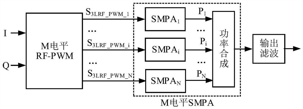
[0107] As a specific embodiment, a specific harmonic elimination 5-level RF-PWM modulator includes: a pulse delay control unit, a radio frequency carrier pulse generation unit, first to fourth digital delay line units, first to The second inverter, the first to fourth delay compensation units, and the first to second two-way multiplexers have the first to third three signal input terminals and the first to fourth four signal output terminals in total. , to achieve specific harmonic elimination 5-level RF PWM, and the generated 5-level RF PWM signal S 5LRF_PWM Converted to 3-level RF pulse width modulation signal S with 2 channels of equal pulse area 3LRF_PWM_1 and S 3LRF_PWM_2 , using the digital delay line unit to generate phase-shift control signals for driving the subsequent SMPA unit, so as to achieve power balance between the two SMPAs and between the power tubes in the unit, where:
[0108] The pulse delay control unit includes first to second signal input terminals, f...
Embodiment
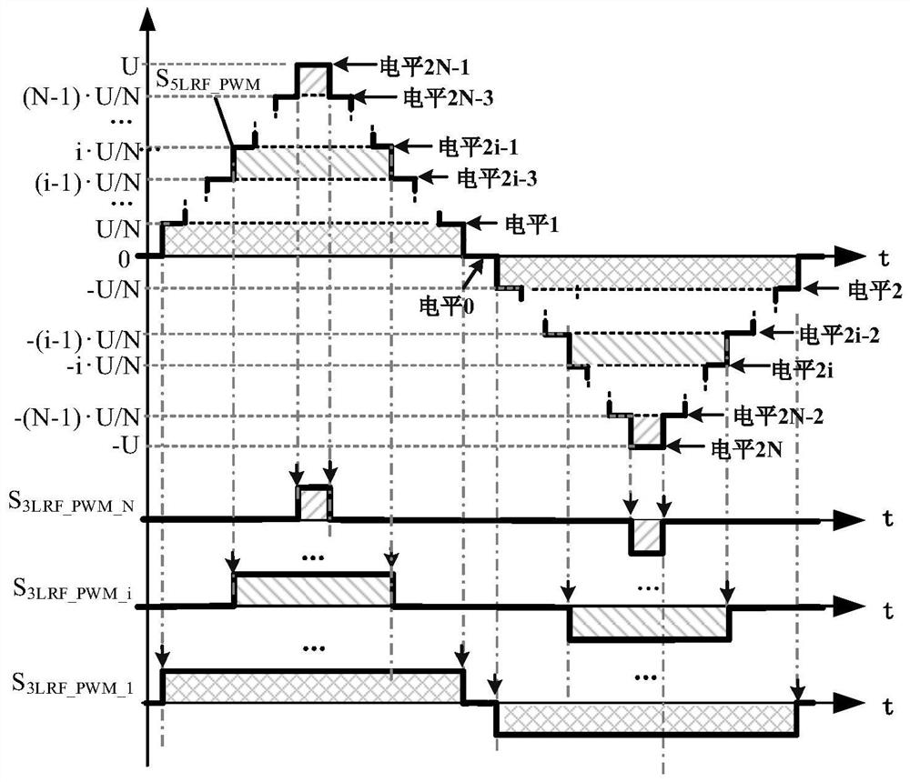
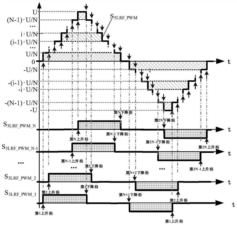
[0137] Such as image 3 As shown, according to the pulse rising and falling edges of the output multi-level RF-PWM pulse signal, the specific harmonic elimination multi-level RF-PWM output sequence is decomposed into multiple 3-level RF-PWM pulse sequences with equal pulse areas, To drive the subsequent SMPA unit. The present invention is based on a specific harmonic elimination multi-level RF-PWM method, and outputs an M-level RF-PWM signal S MLRF_PWM , M is any odd number greater than 3, and its normalized maximum level amplitude is U, then the corresponding amplitudes of M levels are -U, ..., -iU / N, ..., -U / N, 0, U / N,...,iU / N,...,U, N=(M-1) / 2, i is any integer between 1 and N, M level RF-PWM signal S MLRF_PWM Contains M-1 pulse rising edges and M-1 pulse falling edges, which are defined as the first pulse rising edge, the second pulse rising edge, ..., the i-th pulse according to the time sequence of pulse rising or falling edges Rising edge, ..., the rising edge of the...
PUM
 Abstract
Description
Claims
Application Information
 - Generate Ideas
- Intellectual Property
- Life Sciences
- Materials
- Tech Scout
- Unparalleled Data Quality
- Higher Quality Content
- 60% Fewer Hallucinations
Browse by: Latest US Patents, China's latest patents, Technical Efficacy Thesaurus, Application Domain, Technology Topic, Popular Technical Reports.
© 2025 PatSnap. All rights reserved.Legal|Privacy policy|Modern Slavery Act Transparency Statement|Sitemap|About US| Contact US: help@patsnap.com


