
Coupling reactor high-voltage direct current fault current limiter

A coupled reactance, high-voltage DC technology, used in emergency protection circuit devices, electrical components, circuit devices, etc. for limiting overcurrent/overvoltage, can solve the problems of difficulty in breaking large fault currents and high energy absorption of arresters, achieving The effect of reducing the capacity of a single capacitor, improving economic efficiency and improving service life

Pending Publication Date: 2019-03-19
HUAZHONG UNIV OF SCI & TECH
View PDF0 Cites 3 Cited by
  • Summary
  • Abstract
  • Description
  • Claims
  • Application Information

AI Technical Summary

Problems solved by technology

[0004] Aiming at the above defects or improvement needs of the prior art, the present invention provides a coupling reactor type high-voltage DC current limiter, which aims to solve the problems in the prior art due to the difficulty in breaking large fault currents and the arrester absorption caused by breaking large fault currents. high technical issues

Method used


Image

  • Coupling reactor high-voltage direct current fault current limiter
  • Coupling reactor high-voltage direct current fault current limiter
  • Coupling reactor high-voltage direct current fault current limiter

Examples


Embodiment Construction

[0018] In order to make the object, technical solution and advantages of the present invention clearer, the present invention will be further described in detail below in conjunction with the accompanying drawings and embodiments. It should be understood that the specific examples described here are only used to explain the present invention, not to limit the present invention. In addition, the technical features involved in the various embodiments of the present invention described below can be combined with each other as long as they do not constitute a conflict with each other.

[0019] The purpose of the present invention is to provide a coupling reactor type high-voltage DC current limiter, which aims to ensure that the high-voltage DC circuit breaker itself operates quickly, breaks large currents and withstands high voltages, and can limit the voltage on the high-voltage side during faults and reduce Break the current, reduce the energy absorption, and increase the relia...


PUM


Abstract

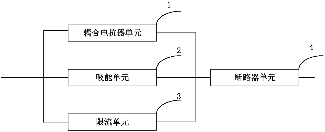
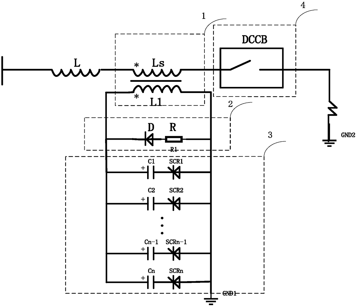
The invention provides a coupling reactor high-voltage direct current fault current limiter. The coupling reactor high-voltage direct current fault current limiter comprises: a coupling reactor unit,a current limiting unit, an energy absorbing unit and a DC circuit breaker unit. The coupling reactor unit is composed of a coupled reactor and a line. When a short trouble is generated, the primary inductor of the coupling reactor and the precharge capacitor of the current limiting unit oscillate, a negative voltage is generated at the secondary side to reduce the current required to be cut off and the line inductor initial energy, and the secondary inductor is the line flat-wave inductor; when the fault occurs, the current limiting unit cooperates with the coupling reactor to generate a negative voltage on the line side; the energy absorbing unit is a diode in serial connection with the resistor to suppress the primary side inductor energy to be transmitted to the secondary side of the coupling reactor; the DC circuit breaker unit includes a DC breaker and a lightning arrester, the breaker cut off the fault current, and the arrester absorbs the energy stored by the inductor. The coupling reactor high-voltage direct current fault current limiter provided by the invention achieves the control of the fault current and the energy absorption limit of the lightning arrester, the capacitor parallel connection reduces the capacity and the cost is low.

Description

technical field [0001] The invention belongs to the field of high-voltage direct-current current limiters, and more specifically relates to a high-voltage direct-current current limiter with coupling reactors. Background technique [0002] Due to the shortage of traditional fossil energy, the aggravation of environmental pollution and the continuous growth of users' demand for electric energy, the development of renewable energy and clean energy has developed rapidly. In order to obtain long-distance renewable energy such as wind energy and solar energy more economically, based on the advantages of low loss, long-distance, high-power transmission, more efficient connection of renewable energy to the grid and flexible operation, the advantage of direct current transmission is that it does not increase the system. The short-circuit capacity facilitates the asynchronous network operation of two major power systems and the network connection of power systems with different frequ...

Claims


Application Information

Patent Timeline
IPC IPC(8): H02H9/02
CPCH02H9/021
Inventor 陈立学袁召潘垣何俊佳
Owner HUAZHONG UNIV OF SCI & TECH
Learn More