
A computer vision-based automatic monitoring method for grain storage quantity change in granary

A computer vision and quantity change technology, applied in computer parts, computing, data processing applications, etc., can solve the problems of high energy consumption and time cost, and achieve the effect of fast detection speed and low energy consumption

Active Publication Date: 2019-03-15
HENAN UNIVERSITY OF TECHNOLOGY
View PDF8 Cites 12 Cited by
  • Summary
  • Abstract
  • Description
  • Claims
  • Application Information

AI Technical Summary

Problems solved by technology

[0007] The purpose of the present invention is to solve the problem that the existing monitoring method for the quantity of stored grain needs to continuously detect the quantity of grain in the entire granary, resulting in high energy consumption and high time cost

Method used


Image

  • A computer vision-based automatic monitoring method for grain storage quantity change in granary
  • A computer vision-based automatic monitoring method for grain storage quantity change in granary
  • A computer vision-based automatic monitoring method for grain storage quantity change in granary

Examples


Embodiment 1

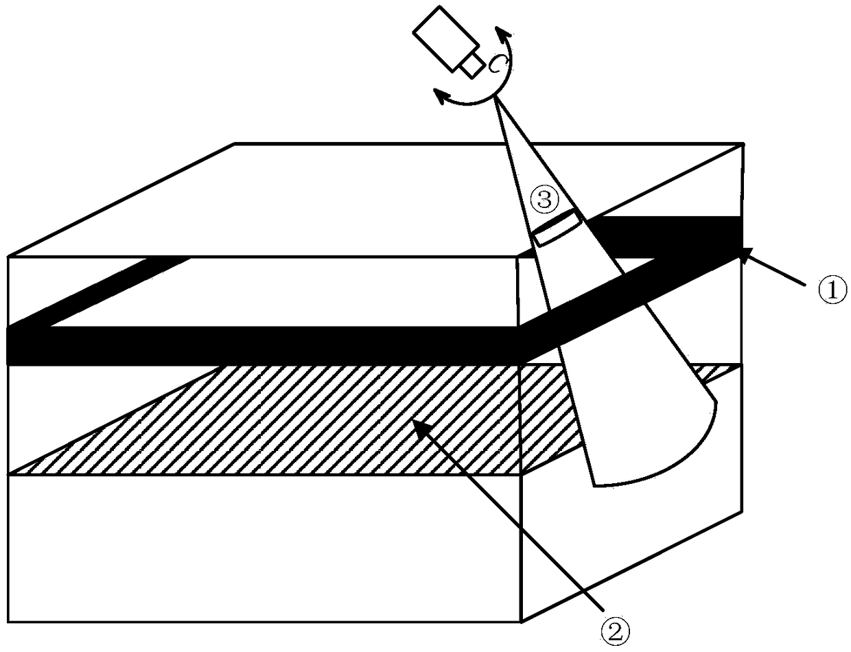
[0026] figure 1 It is a schematic diagram of the monitoring framework of the embodiment of the present invention, as shown in the figure: it includes a camera C, a grain loading line ①, a grain surface ② and a grain outlet ③; the grain loading line ① is distributed around the granary. Among them, the camera C is used to obtain the image of the grain loading line ① and the grain surface ② at the grain outlet ③ of the granary.

[0027] In other embodiments, the grain loading line can be replaced with a marking line, for example: it can be replaced with a marking line set 20-50 cm above the grain loading line; it can also be replaced with a marking set at other corresponding positions according to monitoring needs Wire. If the marking line is used, all the grain loading lines in the subsequent description can be replaced with the marking line, and the methods and steps involved are the same. Among them, both the grain loading line and the marking line are reference lines, which...

Embodiment 2

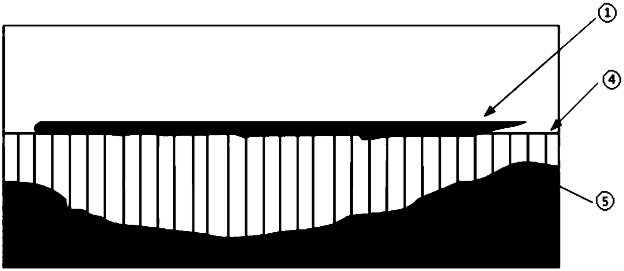
[0065] In this embodiment, the only difference from Embodiment 1 is that when calculating the overall height of the grain surface, the area between the grain loading line and the grain surface is used. The calculation steps are as follows: first, calculate the boundary of each pixel on the grain surface The vertical distance between the point and the straight line of the lower boundary of the fitted grain loading line; then, use the integral method to calculate the area between the grain loading line and the grain surface to obtain the overall height of the grain surface.

[0066] After obtaining the overall height of the grain noodles, compare the overall height of the current grain noodles with the overall height of the grain noodles recorded in history. If the difference between the two is greater than the set threshold, an alarm will be sent to the management personnel; otherwise, the current data will be recorded . For example: Suppose the area from the current grain load...


PUM


Abstract

The invention provides an automatic monitoring method of grain storage quantity change based on computer vision, belonging to the technical field of grain storage detection. The invention firstly collects the grain surface image at the grain mouth; The grain surface image comprises a reference line above the grain ration surface, wherein the reference line is a grain loading line or a marking line; The whole height of the grain surface is calculated by processing the grain surface image, and is compared with the whole height of the grain surface calculated at a predetermined time or at a previous time; If the overall height of the grain surface drops, the amount of stored grain in the warehouse is judged to be reduced. As oppose to that prior art which requires the continuous detection ofthe amount of grain in the entire granary, The invention only needs to detect the grain surface information at the grain mouth, and compares the calculated whole grain surface height with the preset primary or previous calculation result, so as to judge whether the grain storage quantity in the granary is changed, and has the advantages of fast detection speed and low energy consumption.

Description

technical field [0001] The invention relates to a computer vision-based automatic monitoring method for changes in the quantity of grain stored in granaries, and belongs to the technical field of granary detection. Background technique [0002] In recent years, with the intelligent construction of grain depots, in order to accurately grasp and analyze the grain situation in the granary, the commonly used technologies mainly include the detection method of stored grain quantity based on pressure sensor, the detection method of stored grain quantity based on infrared laser scanning and the method based on Storage grain quantity detection method based on ground penetrating radar. Compared with the traditional manual warehouse clearance and inspection, these methods have improved the efficiency and detection accuracy of warehouse clearance and inspection, but there are still some shortcomings. For example, the method based on pressure sensors has higher requirements for the layo...

Claims


Application Information

Patent Timeline
Patent Type & Authority Applications(China)
IPC IPC(8): G06K9/34G06K9/62G06Q10/08
CPCG06Q10/087G06V10/267G06F18/2411G06F18/214
Inventor 李磊董卓莉费选赵晨阳张永威王峰
Owner HENAN UNIVERSITY OF TECHNOLOGY
Learn More