A new method of structural mesh generation

A grid generation and new structure technology, applied in image data processing, special data processing applications, 3D modeling, etc., can solve the problems of grid splicing trouble, waste of time, grid dependence on manual control, etc., to reduce human labor. Dependent, high computational precision effects

Active Publication Date: 2019-03-12
CALCULATION AERODYNAMICS INST CHINA AERODYNAMICS RES & DEV CENT
View PDF1 Cites 2 Cited by
  • Summary
  • Abstract
  • Description
  • Claims
  • Application Information

AI Technical Summary

Problems solved by technology

The traditional structural grid generation method can generate high-quality single-block structural grids for simple areas, but with the development of science and technology, it is necessary to solve more and more complex and fine models. The traditional method can only be the complex area first. Partition, and then generate grids separately. Grid splicing between different areas is very troublesome. Grid generation relies too much on manual control, which is a waste of time
In practical CFD engineering applications, it is often desirable to generate high-quality structural meshes conveniently and efficiently, but there is no effective method to automatically generate high-quality structural meshes

Method used


Image

  • A new method of structural mesh generation
  • A new method of structural mesh generation
  • A new method of structural mesh generation

Examples


Embodiment

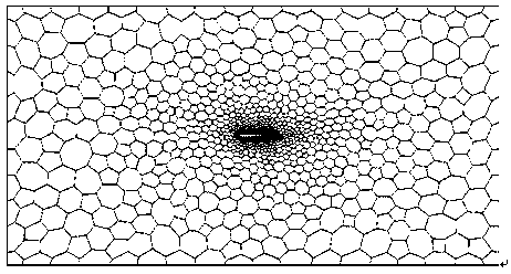
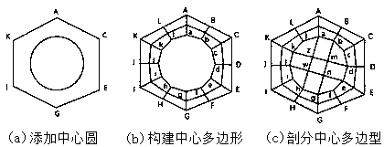
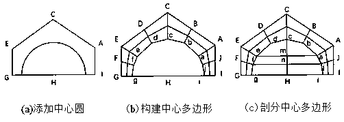
[0041] The present invention generates structured grids based on the existing Delaunay triangulation technology. First, read in the model data to obtain the discrete point set and boundary information of the calculation area; secondly, perform Delaunay triangulation on the calculation area; then, use the triangular grid to generate a transition grid: optimized Voronoi diagram; finally judge the transition grid Unit type, the center circle method is used to divide the grid unit to generate a structural grid.

specific Embodiment approach

[0043] First, read the data file of the model through a specific data interface, then analyze the data file, and then extract the discrete point set and boundary information of the calculation area, and store it in the corresponding data structure for the next step enter.

[0044] Generate a triangulated mesh:

[0045] (1) Input the discrete point set and boundary information of the calculation area, construct a super triangle, including all discrete points, and put it into the triangle list;

[0046] (2) Insert the discrete points in the point set one by one, and find out the triangle whose circumcircle contains the insertion point in the triangle linked list, which is called the influence triangle of the point; delete the common side of the influence triangle, and use the input point to affect all the triangles The vertices are connected to complete the insertion in a Delaunay triangle list;

[0047] (3) Optimize the locally newly formed triangles according to the optimiza...


PUM


Abstract

The invention provides a novel structural mesh generation method, which is based on an existing Delaunay triangulation technology to generate a structural mesh. Firstly, the discrete point set and boundary information of the computational region are obtained by reading the model data. Secondly, Delaunay triangulation is applied to the computational region. Then, the triangular mesh is used to generate the transitional mesh: the optimized Voronoi diagram; Finally, the transitional mesh element type is judged, and the mesh element is divided by the central circle method to generate the structured mesh. The invention can realize the automatic generation of the structural mesh of the complex region, and has high calculation precision, and reduces the dependence on human being compared with thetraditional method. Delauny triangulation technology is a mature unstructured mesh generation technology, which can generate adaptive and locally refined high-quality mesh for complex regions efficiently and quickly. This method adopts triangulated mesh as background mesh, so it can also realize mesh adaptation and local refinement.

Description

technical field [0001] The present invention relates to the technical field of pre-processing structural grid generation of computational fluid dynamics (abbreviated as CFD), in particular to a novel structural grid generation method. Background technique [0002] The automatic generation of structural meshes of two-dimensional complex shapes has always been one of the bottlenecks hindering the application of CFD engineering. The traditional structural grid generation method can generate high-quality single-block structural grids for simple areas, but with the development of science and technology, it is necessary to solve more and more complex and fine models. The traditional method can only be the complex area first. Partitioning, and then generating grids separately, grid splicing between different areas is very troublesome, and grid generation relies too much on manual control, which is a waste of time. In practical CFD engineering applications, it is often desired to g...

Claims


Application Information

Patent Timeline
IPC IPC(8): G06T17/30G06F17/50
CPCG06T17/30G06F30/20
Inventor 庞宇飞王子维齐龙胡月凡卢风顺黄尚坤缪涛陈波潘艳
Owner CALCULATION AERODYNAMICS INST CHINA AERODYNAMICS RES & DEV CENT
Why Eureka
Try Eureka