


Quick Research
Generate reliable direction feasibility study reports for your R&D in just a few steps.

Technical Q&A
Discover and master advanced knowledge NOW. Basics, ideas, possibilities, all at once.

Find Solutions
As an expert in R&D theories, this can generate solutions to your technical problems instantly.

Evaluate Feasibility
Analyze your overall solution with one click, know your potential R&D risks in advance.

Monitor Landscape
Get weekly tech updates, stay abreast of the latest tech innovations and key insights.
Regenerative burner capable of being conveniently installed and disassembled
A regenerative and regenerative technology, applied in burners, combustion methods, waste heat treatment, etc., can solve the problems of complex process, inconvenient installation and disassembly, and large installation workload, and achieve convenient installation, reduce alignment procedures, and quickly The effect of installation
- Summary
- Abstract
- Description
- Claims
- Application Information
AI Technical Summary
Problems solved by technology
Method used
Image

Examples
Embodiment 1
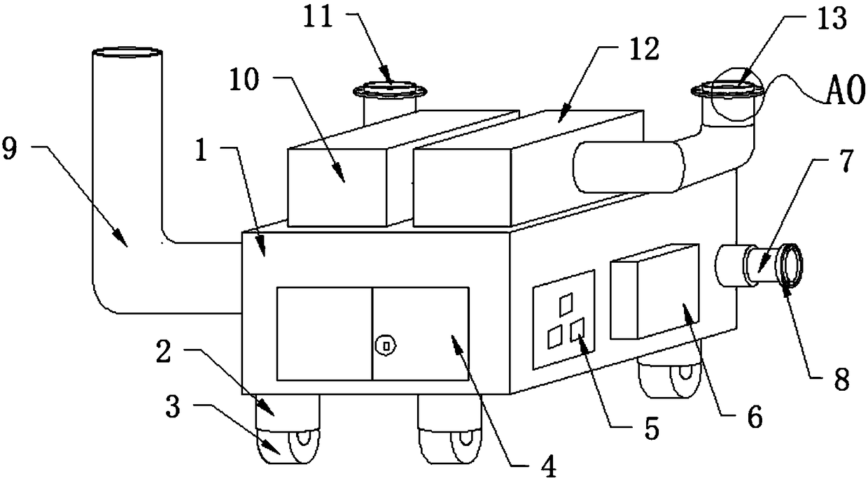
[0018] see Figure 1-Figure 3 As shown, it can be implemented as follows:
[0019] A regenerative burner that is easy to load and disassemble includes a shell 1, the side of the shell 1 is provided with an inspection door 4, the inspection door 4 is covered and arranged on the shell 1, and is fixedly connected with the shell 1 by bolts, the shell 1 The junction box 5 and the FX-32 blower 6 are respectively arranged on the side, and the junction box 5 and the FX-32 blower 6 are both covered and arranged on the housing 1, and are fixedly connected with the housing 1 by bolts, and the junction box 5 and the FX-32 The blower 6 is electrically connected. The FX-32 blower 6 has a valve stem 7 on one side, and the valve stem 7 is embedded in the housing 1. One end of the valve stem 7 is provided with a valve handle 8, and one side of the housing 1 is provided with a drain. The smoke pipe 9 and the smoke exhaust pipe 9 are embedded in the casing 1, and the top of the casing 1 is resp...
Embodiment 2
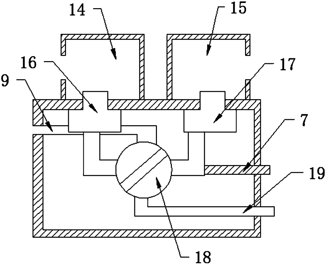
[0021] The present invention provides a technical solution: the difference from Embodiment 1 is: after the virtual heat of the second regenerator 17 reaches a certain degree, use the valve handle 8 to turn the reversing valve 18 to change the air flow direction, and the air will pass through the second regenerator The second regenerator 17 enters the second regenerator 12 and burns in the regenerator 12, the heat enters the industrial furnace, and the high-calorie smoke in the industrial furnace enters the reversing valve 18 from the first regenerator 10 , and then discharged through the exhaust pipe 9.
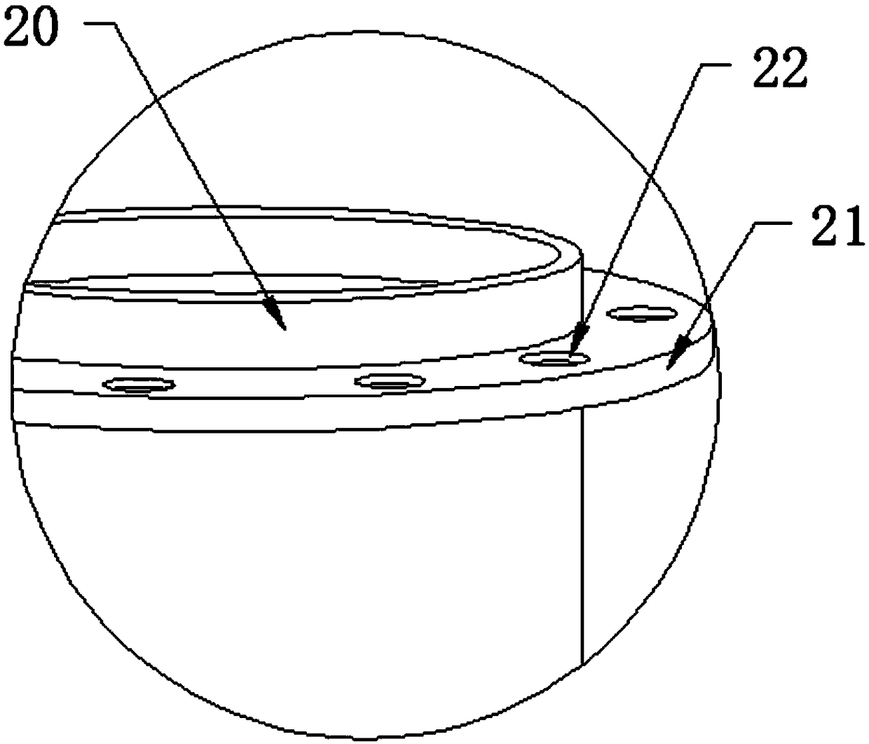
[0022] The working principle of a regenerative burner that is easy to load and disassemble: when in use, use the universal wheel 3 to move the burner to the bottom of the industrial furnace, and place the ring pad 20 on the top of the first burner 11 and the second burner 13 Insert it into the upper interface of the industrial furnace, and then use the installation ring 21 an...
PUM
 Abstract
Description
Claims
Application Information
 - R&D Engineer
- R&D Manager
- IP Professional
- Industry Leading Data Capabilities
- Powerful AI technology
- Patent DNA Extraction
Browse by: Latest US Patents, China's latest patents, Technical Efficacy Thesaurus, Application Domain, Technology Topic, Popular Technical Reports.
© 2024 PatSnap. All rights reserved.Legal|Privacy policy|Modern Slavery Act Transparency Statement|Sitemap|About US| Contact US: help@patsnap.com